Last year I made (and posted) a cart based on Jody's open frame concept made from 1-1/2" square tube. I have plenty of 1-1/4" sched 40 pipe on the rack, castors off a junked display fridge, and wheels off an axial man cooler so I have the materials to make another one out of pipe when (and if) I get the time. Started looking everywhere for templates for pipe XYZ corner joints and couldn't find any. Anyone know of the existence of these?
Anyway I decided to make my own template and I post my results here if anyone is interested or has a use. Could be good for furniture or anything. Maybe someone has a better, faster way of doing it.
First tacked together a bandsaw cut mitre joint for X-Y positions

- X2.jpg (46.26 KiB) Viewed 606 times
Then tacked a square cut piece into Z position with pipe wrap chalk mark.
- X7.jpg (38.02 KiB) Viewed 606 times
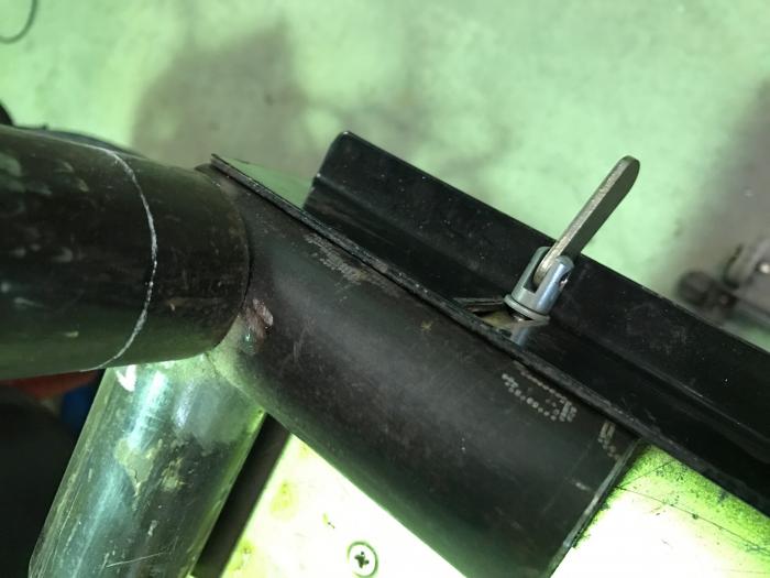
and used a piece of tig wire to transpose measurements to paper from chalk line to touch point of X-Y pieces at various points around the Z pipe to make a wrap template.
This is the result:

- X1.jpg (68.67 KiB) Viewed 606 times
And this is what the Z pipe looks like (cut with a worn 5" wafer disc):

- X6.jpg (53.13 KiB) Viewed 606 times
And fits like a glove:

- X3.jpg (52.01 KiB) Viewed 606 times