I am finally getting around to installing some air lines in my shop. I am going to plumb them in copper and was wondering if anyone had any recommendations as to whether I should be using silver solder or just regular plumbing solder.
It seems that there are a lot of differing opinions on this, but no real definitive answer.
Thanks.
General welding questions that dont fit in TIG, MIG, Stick, or Certification etc.

- Otto Nobedder
-
Weldmonger

-
Posts:
-
Joined:Thu Jan 06, 2011 11:40 pm
-
Location:Near New Orleans
Plumbing solder is just fine for this...
We ran a buried 1" line for nitrogen and used silver only because it was a) buried, and b) needed to be rated for 250PSI, but that was insurance against having to dig it up.
A "sweat copper" joint with plumber's solder is rated the same as the pipe it's on, so, no worries.
Steve S
We ran a buried 1" line for nitrogen and used silver only because it was a) buried, and b) needed to be rated for 250PSI, but that was insurance against having to dig it up.
A "sweat copper" joint with plumber's solder is rated the same as the pipe it's on, so, no worries.
Steve S
450dualsport
- 450dualsport
-
Guide

-
Posts:
-
Joined:Wed Oct 30, 2013 10:46 am
Thanks Steve. I was hoping you would have some input on this.
Thanks mfletch, I'm glad to hear your system has been holding up. My single stage compressor only puts out 110 psi at the outlet as well. Most air tools only run at 90 psi anyway.
Plumber's solder it is then!
Googling this topic is almost as bad as Googling "what motor oil should I use"?
Thanks mfletch, I'm glad to hear your system has been holding up. My single stage compressor only puts out 110 psi at the outlet as well. Most air tools only run at 90 psi anyway.
Plumber's solder it is then!
Googling this topic is almost as bad as Googling "what motor oil should I use"?

I just finished plumbing my shop with type L 1/2" copper and cast 1/2" outlets. I used common silver-bearing plumber's solder (you can get higher PSI ratings with other types). But did pickup a few pointers on layout that might be useful...
* I added a ball valve at the tank because the quick-disconnect fittings bleed the line over time. This keeps the compressor always at the ready, and it also won't kick on in the middle of the night.
* If you're not installing a commercial air dryer (yeah, right), find a way to cool and slow the air so the water vapor will condense before it hits the air filter / water trap, or it'll pass right through. Right out of the tank, I did a radiator layout with an input header at the top and the outlet header at the bottom, with several 1/2" lines between them; other guys have done a single zig-zag line.
* Even then, plan for moisture to collect in the line. Have drip legs at low points, and have your outlets point up (or at least loop up), not down (so the tool outlet doesn't become a drip leg). Ideally, slope your lines so they lead to these drip traps.
* Run the line at tank pressure (no regulator). Fit an inline regulator with quick disconnect fittings and maybe a lead-in hose to use closer to tools as you connect them. That way tools that need high CFM won't be choked by a regulator at the tank (even at full-open).
* Plan some high-flow connectors for your heavy impact guns - they'll run a lot better with 1/2" hose and 3/8" fittings.
* Look at buying your joints and fittings online in bulk (e.g., eBay). You'll find sources for the same Nibco parts, but they'll be a fraction of the retail price.
* I used heavy "split ring" mounting anchors on the outlets because they're going to get a lot of yanking from hoses. Lowe's sells them at a competitive price.
If you're interested, I can post some pics and a few more details.
For what it's worth,
Richard
Last edited by RichardH on Fri Jan 24, 2014 7:48 pm, edited 1 time in total.
Grinding discs... still my #1 consumable!
450dualsport
- 450dualsport
-
Guide
-
Posts:
-
Joined:Wed Oct 30, 2013 10:46 am
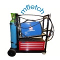
My system is going to be pretty simple.I am installing a desiccant air dryer, a filter and two outlets.
If it's not too much trouble and you don't mind, I'd be interested in seeing some pics of your system. I'm sure others would too.
If it's not too much trouble and you don't mind, I'd be interested in seeing some pics of your system. I'm sure others would too.
Here's the condenser setup. It's about 48" tall, and the bottom header uses 45-degree fittings to slope toward the filter on the outlet. (Tucked behind the compressor, so I couldn't get it in the pic.) The compressor outlet is a 1/2" which I step up to 3/4 for the lead-in hose and feed into the top header.
There's no science to the measurements here; it's based on available space, and the goal is just to have more surface area to transfer heat and larger overall pipe size to slow the flow rate, to allow condensation.
An alternative is to place filters near the outlets / equipment, in which case the main piping does much of the same effect.
This is what I meant by the outlet anchors. They come in standard pipe sizes; the line here is 1/2", but I wanted to solidly mount it via the cast fitting so I used a 3/4" anchor and had the anchor bolt protrude into the 3/4" opening and press against the backside of the fitting to get a solid fit.
The split-ring hangers use a 3/8" thread, so it needs a "hanger bolt" to screw it into a stud - wood screw on one end and machine thread on the other. Like the split hangers, Lowe's also sells these bolts for a sane price; Home Depot does not. I'll post a separate reply with my trick for installing them.
I wanted the outlets to point down and out at an angle (~30 degrees from the wall) rather than straight out from the wall. The funny loop there is so the tee points anywhere but down, for condensation in the line (the loop is just an L on vertical sections). And I used street elbows to clean it up a little. I opted for cast fitting because I wanted something that could be more ruggedly anchored than a copper NPT fitting (no soldered joints taking stress here).
Cheers,
Richard
There's no science to the measurements here; it's based on available space, and the goal is just to have more surface area to transfer heat and larger overall pipe size to slow the flow rate, to allow condensation.
An alternative is to place filters near the outlets / equipment, in which case the main piping does much of the same effect.
- Condenser tubing
- Air line condenser.jpg (85.7 KiB) Viewed 1551 times
- Anchoring the outlets
- Air line outlet.jpg (51.04 KiB) Viewed 1551 times
I wanted the outlets to point down and out at an angle (~30 degrees from the wall) rather than straight out from the wall. The funny loop there is so the tee points anywhere but down, for condensation in the line (the loop is just an L on vertical sections). And I used street elbows to clean it up a little. I opted for cast fitting because I wanted something that could be more ruggedly anchored than a copper NPT fitting (no soldered joints taking stress here).
Cheers,
Richard
Last edited by RichardH on Fri Jan 24, 2014 7:59 pm, edited 2 times in total.
Grinding discs... still my #1 consumable!

RichardH wrote:
* I added a ball valve at the tank because the quick-disconnect fittings bleed the line over time. This keeps the compressor always at the ready, and it also won't kick on in the middle of the night.
For what it's worth,
Richard
Move this to the top of the list!
Look! a hole in the space-time continuum!
Good suggestion - done!cornmuse wrote: Move this to the top of the list!
That's one of the easiest, most practical things I've done to my system. Even a portable compressor setup will benefit from doing this.
Last edited by RichardH on Fri Jan 24, 2014 7:49 pm, edited 1 time in total.
Grinding discs... still my #1 consumable!
450dualsport
- 450dualsport
-
Guide
-
Posts:
-
Joined:Wed Oct 30, 2013 10:46 am
Here's a little more detail on those split-ring hangers. You'd want the copper-plated ones to prevent galvanic corrosion.
http://www.lowes.com/pd_301343-34146-AV ... Id=3223455
The 3/8" thread is a doozy if you're not hanging them from all-thread like normal. Here's the hanger bolt it takes to fasten it into a stud:
They only come in 3" lengths. Lowe's has them on the pegboard for a decent price. They're a pricey specialty bolt at Home Depot. At this size, you need a pilot hole (perhaps 3/16"), and you want to shoot for the center of the stud.
Driving them into the wall is the challenge, because I wanted the split-ring hanger to be mounted flush. I started with a double-nut setup, where they were locked together and I drove against the outer nut, but that couldn't get flush enough.
I settled on this setup - it's a 3/8" coupler nut with a 3/8" bolt inserted as a stop. The hanger bolt can only thread into it so far, then the whole setup is driven with an impact gun until the coupler nut is flush at the wall. The hex head is a touch smaller than the coupler nut, but big enough that it couldn't turn in the deep-well socket. The stop bolt is marked for depth. This setup worked really well.
Cheers,
Richard
http://www.lowes.com/pd_301343-34146-AV ... Id=3223455
- Split-ring hanger.jpg (48.24 KiB) Viewed 1084 times
- Hanger bolt.jpg (38.48 KiB) Viewed 1084 times
Driving them into the wall is the challenge, because I wanted the split-ring hanger to be mounted flush. I started with a double-nut setup, where they were locked together and I drove against the outer nut, but that couldn't get flush enough.
I settled on this setup - it's a 3/8" coupler nut with a 3/8" bolt inserted as a stop. The hanger bolt can only thread into it so far, then the whole setup is driven with an impact gun until the coupler nut is flush at the wall. The hex head is a touch smaller than the coupler nut, but big enough that it couldn't turn in the deep-well socket. The stop bolt is marked for depth. This setup worked really well.
- Impact gun "screwdriver" for hanger bolts
- Driver jig.jpg (39.99 KiB) Viewed 1084 times
Richard
Grinding discs... still my #1 consumable!
- Superiorwelding
-
Weldmonger
-
Posts:
-
Joined:Thu Jan 24, 2013 10:13 pm
-
Location:Eddy, TX
Topic bump.
For this Holiday break from work I would like to tackle a few home and garage projects that have been on my list. One of which is a condenser for my air compressor. I used the search box for "condenser" and this seemed to be the best topic in that search so I thought I would revive it. I know a few others have posted pics of their setups and would ask if they can post pics and advise here, I would appreciate it. One of the house projects is installing a new water softener and where it goes is 3/4" copper line so I made a trip to Lowes and might have bought extra pieces and pipe than I needed. So basically I want a single line zig zag using the 3/4" copper with at least 4 legs and drains at the bottom of each leg. I am not necessarily interested in a budget friendly version except for the desiccant filter which I can make myself. So WerkSpace posted a pic of what I assume is his setup and I noticed he used different diameter piping, what is the reason behind that and is it necessary? If not I will stick with 3/4". In a former life I helped make copper condensers for a customer but we made them to print. They used 3/4" or 1" copper and we would just cut the pipe to length, solder them together, pressure test them and polish them up. Also, for the moment all I have in the garage is a small 120v compressor that actually came out of a dentist office years ago, man is it quiet. I want to build this as if I still had my big air compressor. Any advise will be greatly appreciated.
-Jonathan
For this Holiday break from work I would like to tackle a few home and garage projects that have been on my list. One of which is a condenser for my air compressor. I used the search box for "condenser" and this seemed to be the best topic in that search so I thought I would revive it. I know a few others have posted pics of their setups and would ask if they can post pics and advise here, I would appreciate it. One of the house projects is installing a new water softener and where it goes is 3/4" copper line so I made a trip to Lowes and might have bought extra pieces and pipe than I needed.
-Jonathan
Instagram- @superiorwelding/@learntotig
Twitter- @_JonathanLewis
https://www.learntotig.com
https://www.superiorweldandfab.com
https://www.youtube.com/+SuperiorWeldin ... ATHANLEWIS
Twitter- @_JonathanLewis
https://www.learntotig.com
https://www.superiorweldandfab.com
https://www.youtube.com/+SuperiorWeldin ... ATHANLEWIS
- Superiorwelding
-
Weldmonger
-
Posts:
-
Joined:Thu Jan 24, 2013 10:13 pm
-
Location:Eddy, TX
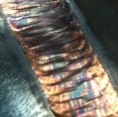
Here is the mock up. The runners are 30" with 6" spacing between. I cleaned the inside of the pipes like our hydraulic suppliers do, blowing a squeegee down each tube. Don't want the copper dust ruining my Harbor Freight die grinders. The fittings on the end are only there for this pic and are not what will be used when it is mounted. I have brass valves at the shop to put on the inlet and outlet so I can detach from this if I want to. I remembered that I had this little desiccant filter from my painting days and included it in the mock up as well. I will need to dry the beads for sure. So besides a few small changes what does everyone think? Any changes? Will start putting it together tomorrow.
-Jonathan
-Jonathan
- Attachments
-
- image.jpg (116.72 KiB) Viewed 1034 times
Instagram- @superiorwelding/@learntotig
Twitter- @_JonathanLewis
https://www.learntotig.com
https://www.superiorweldandfab.com
https://www.youtube.com/+SuperiorWeldin ... ATHANLEWIS
Twitter- @_JonathanLewis
https://www.learntotig.com
https://www.superiorweldandfab.com
https://www.youtube.com/+SuperiorWeldin ... ATHANLEWIS
I would shorten the spacer pipes between the elbows as much as possible to reduce the overall size. Airflow over this condenser will increase condensation significantly. If you don't want an electric fan, try mounting one to your compressor pulley and mount to condenser in the air flow path.
Cheers,
Vic.
Cheers,
Vic.
Flat out like a lizard drinkin'
- Otto Nobedder
-
Weldmonger
-
Posts:
-
Joined:Thu Jan 06, 2011 11:40 pm
-
Location:Near New Orleans
I like Coldman's idea, shortening the horizontal legs.
I'd size them to fit the width of the outlet of my shop's air conditioner.
The more "cool" you can add to that loop (Okay, the more heat you can extract from that loop), the more effective it will be. There's also no reason not to dump all four legs to a common manifold with a single drain.
Steve S
I'd size them to fit the width of the outlet of my shop's air conditioner.
The more "cool" you can add to that loop (Okay, the more heat you can extract from that loop), the more effective it will be. There's also no reason not to dump all four legs to a common manifold with a single drain.
Steve S
- Superiorwelding
-
Weldmonger
-
Posts:
-
Joined:Thu Jan 24, 2013 10:13 pm
-
Location:Eddy, TX
Vic and Steve,
Sounds like a plan. Having company this weekend has not allowed me any time to get out there to play with it. Will have to get back to Lowes for a few more "T's". My father in law was wanting to watch my solder as he never did it before. That supposed me. Maybe we can get out there in the morning.
-Jonathan
Instagram- @superiorwelding/@learntotig
Twitter- @_JonathanLewis
https://www.learntotig.com
https://www.superiorweldandfab.com
https://www.youtube.com/+SuperiorWeldin ... ATHANLEWIS
Twitter- @_JonathanLewis
https://www.learntotig.com
https://www.superiorweldandfab.com
https://www.youtube.com/+SuperiorWeldin ... ATHANLEWIS


True a single drain valve could be used, although you'd still want some sort of block-valves in the individual drain pipes between the condenser stages/loops to stop the air from taking the easy/shortest path through the intended 'drain' pipe from the input to the exit instead of going through the whole condenser.Coldman wrote:Also you can joint the drain legs together and have one drain valve instead of 4.
Fluids and gasses are quite lazy and if there's a less restrictive (usually shorter) path available they will take that. Somehow compressed air doesn't pay any attention to the signs saying that it should not go through the drain path..
Bye, Arno.
- Superiorwelding
-
Weldmonger
-
Posts:
-
Joined:Thu Jan 24, 2013 10:13 pm
-
Location:Eddy, TX
Thanks Arno! Coldman, I thought of this when we went out to out it together. In the end it looks exactly like pictured before. I mis-spoke when I said the horizontal pipes were 6". They are 3". My father in law did all the soldering, he was excited to do it but the whole time was worried about how many leaks we would have. All those joints and we only had one leak! We also used about 50% more solder than we should but he has to learn somehow. The family and I have been sick the past two days so I haven't been out to garage to get it all cleaned up and mounted, hope to get out of the house tonight or tomorrow.
-Jonathan
-Jonathan
Instagram- @superiorwelding/@learntotig
Twitter- @_JonathanLewis
https://www.learntotig.com
https://www.superiorweldandfab.com
https://www.youtube.com/+SuperiorWeldin ... ATHANLEWIS
Twitter- @_JonathanLewis
https://www.learntotig.com
https://www.superiorweldandfab.com
https://www.youtube.com/+SuperiorWeldin ... ATHANLEWIS
I piped the shop with 3/4" PEX water tubing.
The fittings are all held to the tubing with crimp rings
Copper is fine but the PEX tubing was a significant savings
to my wallet.
I also fashioned a drier out of a 3/4" whole house water filter housing.
You can buy desiccant by the pound but calcium pellets ( Ice-Melt)
seems to work just as well and don't cost squat.
- Otto Nobedder
-
Weldmonger
-
Posts:
-
Joined:Thu Jan 06, 2011 11:40 pm
-
Location:Near New Orleans
If I've NOT mentioned this,
You can plumb every air line in your shop with 1/2" DOT rated nylon air-brake tubing. It's designed for 150 PSI, and certified to 300 PSI, and I've over-pressured it to 450 PSI (on 15 year old sun-exposed tube).
Steve S
You can plumb every air line in your shop with 1/2" DOT rated nylon air-brake tubing. It's designed for 150 PSI, and certified to 300 PSI, and I've over-pressured it to 450 PSI (on 15 year old sun-exposed tube).
Steve S
Return to “Welding Forum General Shop Talk”
Jump to
- Introductions & How to Use the Forum
- ↳ Welcome!
- ↳ Member Introductions
- ↳ How to Use the Forum
- ↳ Moderator Applications
- Welding Discussion
- ↳ Metal Cutting
- ↳ Tig Welding - Tig Welding Aluminum - Tig Welding Techniques - Aluminum Tig Welding
- ↳ Mig and Flux Core - gas metal arc welding & flux cored arc welding
- ↳ Stick Welding/Arc Welding - Shielded Metal Arc Welding
- ↳ Welding Forum General Shop Talk
- ↳ Welding Certification - Stick/Arc Welding, Tig Welding, Mig Welding Certification tests - Welding Tests of all kinds
- ↳ Welding Projects - Welding project Ideas - Welding project plans
- ↳ Product Reviews
- ↳ Fuel Gas Heating
- Welding Tips & Tricks
- ↳ Video Discussion
- ↳ Wish List
- Announcements & Feedback
- ↳ Forum News
- ↳ Suggestions, Feedback and Support
- Welding Marketplace
- ↳ Welding Jobs - Industrial Welding Jobs - Pipe Welding Jobs - Tig Welding Jobs
- ↳ Classifieds - Buy, Sell, Trade Used Welding Equipment
- Welding Resources
- ↳ Tradeshows, Seminars and Events
- ↳ The Welding Library
- ↳ Education Opportunities