
Jody you had said in a video you were trying to figure out how to get spaced ripples the stack of dimes effect. I think we have figured it out. Check these out and let me know.
Steve
Comments & questions on new & past videos

- admin
- Site Admin
-
Posts:
-
Joined:Mon Jun 01, 2009 8:54 am
-
Location:Atlanta, GA
-
Contact:
bluewave wrote:Jody you had said in a video you were trying to figure out how to get spaced ripples the stack of dimes effect. I think we have figured it out. Check these out and let me know.
Steve
Ok. that looks pretty cool. now i am curious about the technique you used.
jody

Would like to give credit where its do. Vick at VKS Fab is the one doing the work.call my style "low & slow", lowest wire speed possible and slow hand speed. Its standard short-circuit mig, one constant bead, no trigger welding here. Dependent upon what type of joint I'm welding I either run "up and back" or "E's" motion. Also, machine wise I run a Lincoln 256 with .030 or A Snap-On MM250 with .035 or .040. With the shop enviroment aroud 40cfms of 75/25
Last edited by bluewave on Fri May 17, 2013 1:30 pm, edited 1 time in total.

This process would make for a great video. Are you able to upload one on to http://www.youtube.com ?
bluewave wrote: call my style "low & slow", lowest wire speed possible and slow hand speed. Its standard short-circuit mig, one constant bead, no trigger welding here. Dependent upon what type of joint I'm welding I either run "up and back" or "E's" motion. Also, machine wise I run a Lincoln 256 with .030 or A Snap-On MM250 with .035 or .040. With the shop enviroment aroud 40cfms of 75/25
Ill see if I can get vick to do a video. Here are more pictures.Post by WerkSpace » Fri May 17, 2013 9:45 am
This process would make for a great video. Are you able to upload one on to http://www.youtube.com ?


Welders watching this and learning need to know how important fit up is for ascetics.

- Otto Nobedder
-
Weldmonger

-
Posts:
-
Joined:Thu Jan 06, 2011 11:40 pm
-
Location:Near New Orleans
Hey, Jody,
If we can get a good enough look at the process, and the settings info, how about a bend test on a butt, peel on a single-side fillet, and maybe a couple of slice-and-etch samples at high and low points in the weld? Maybe even a sledge-hammer test...
I like the "pretty". I don't use this method when it's structurally significant, because I haven't done the tests to prove it. I save it for decorative corners.
Just curious how it stands up to destructive testing.
Otto Nobedder.
Everyone of those interruptions or dips between the dimes is a stress riser. But those risers might mean very little in a negative sense ... especially if there is good fusion. Of course, if the process is running a little cold, then each dime would augment the risk of fusion difficulties. The lengths of the fillet weld legs measured at the dips between the dimes would give us the minimum fillet size. My guess is that the dimes pass will take longer to run than a straight continuous spray pass.
In some ways, the cover passes, become the welders' signatures.
Alexa
- Otto Nobedder
-
Weldmonger
-
Posts:
-
Joined:Thu Jan 06, 2011 11:40 pm
-
Location:Near New Orleans
Alexa,
I agree. I've made the "stress riser" argument discussing TIG welds, particularly socket welds, where walking the cup lends to pretty "tractor tracks".
I've just never seen it analyzed, to see if the common-sense notion of a smooth, uninterupted, even weld and weld interface is actually measurably stronger then "stacks of dimes". I doubt the weld interface is the weak point, if the "dimes" rise and fall smoothly along each leg of the weld. I would sooner suspect low penetration at the "colder" parts of the joint, the space between the larger puddles.
I question it here because the poster referred to "the lowest wire-speed it can tolerate", meaning relatively low weld current, and potentially low penetration. I saw what looked like 1/4" structural parts in there with "pretty" on them, where "strong" is the priority.
If there's been an analysis somewhere, I've not read it, and would be very interested.
Steve S
Otto Nobedder.
Yes ... ensuring fusion is important. If the voltage is not fine tuned on the wire processes there is the risk of lack of fusion.
The drawing may require a minimum sized weld. So those fillet legs, if deposited with dips, the legs would alternate longer and shorter. So if the shorter one is sufficient, then theoretically the longer legs would be excess weld metal.
=====
Perhaps on this string, we are not worried about those calculations and maximizing production, but we are simply discussing the different welding techniques to realize the 'dimes' appearance, for whatever reason.
Alexa
- Otto Nobedder
-
Weldmonger
-
Posts:
-
Joined:Thu Jan 06, 2011 11:40 pm
-
Location:Near New Orleans
Good points.
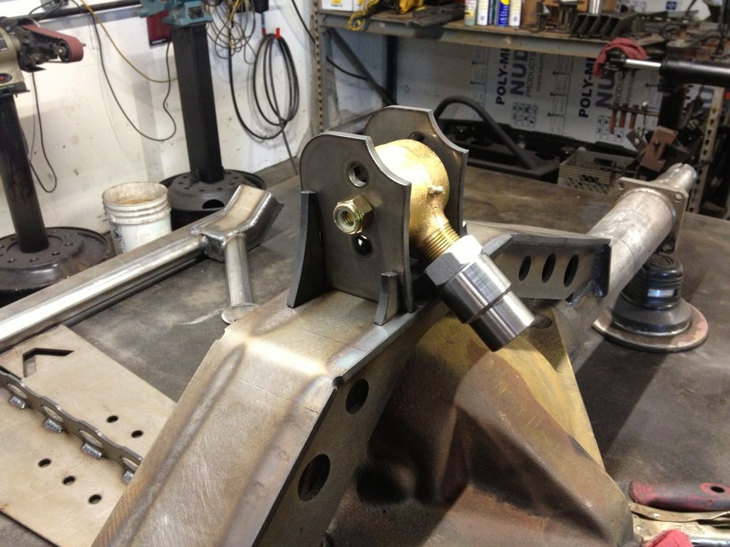
I've reconsidered the use of the welds in the pictures posted. Many, such as on the differential cover, need only be oil-tight, as they're not primary structure. Others, like the link-bar brackets where I noted 1/4" material, are primary structure, but I've seen them done with 1/8" with adequate strength. These may be built with a high enough safety factor that "blazing it in" isn't needed to have more than enough strength.
Your point about matching voltage and wire speed for "ideal" current is well taken, too. The welder clearly knows what he's doing, as evidenced by the consistant beads, lack of any apparent undercut, underfill, or other obvious flaws anywhere in the pictures.
It just raised in me a curiosity about relative strength. Hell, I maybe thinking it backward. The "low and slow" approach allows more heat time on any given location, which may balance penetration while allowing the silicon (appears to be an -S6 wire) more molten time for scavenging.
This discussion really has me thinking.
Thanks, bluewave, for posting!
Steve S
- Otto Nobedder
-
Weldmonger
-
Posts:
-
Joined:Thu Jan 06, 2011 11:40 pm
-
Location:Near New Orleans
- Otto Nobedder
-
Weldmonger
-
Posts:
-
Joined:Thu Jan 06, 2011 11:40 pm
-
Location:Near New Orleans
The "S" in -S6 is for silicon content. The silicon readily combines with impurities, and the silicates formed are less dense than the steel, and rise to the top.
They appear as a glass-like slag on top of the weld, usually tan to dark brown in color.
The challenge is, they don't all make it to the top, and end up as tiny "inclusions" in the weld. I often cut through old MIG welds for repairs, and have to TIG them back up. I can tell the difference between an -S2 weld and an -S6 weld by the amount of crap that cooks out of the weld.
Steve S
I went to apply for a MIG welding job at a place that made cable spool trailers for utility companies. The stacked dime welds were on all of the trailers. He had me run a bead on a lap joint and it came out quite nice as far as MIG welding goes, using the same settings that he had been using. Figured to use what I had been taught in school and a quality weld would surely indicate trainability at least. He said they were looking for the dimes instead, which could have passed for spaced out 6010 whip and pause beads to my eye. I really didn't get the significance other than aesthetic for what would amount to overkill collectively on those trailers with either weld type. Maybe the stacked approach used less wire/faster or something, but he went cold on me for using regular mig passes. You would think if a welder could get perfect edges, convexity etc, that would be a plus, but there was no information in the job application saying they were looking for a specific type of MIG weld. He acted as if all utility trailers everywhere got these beads and that I should know better or something.
Miller ABP 330, Syncrowave 250, Dynasty 300 DX.
Honorary member of the Fraternity of Faded Tee Shirts.
Honorary member of the Fraternity of Faded Tee Shirts.
====TamJeff wrote:I went to apply for a MIG welding job at a place that made cable spool trailers for utility companies. The stacked dime welds were on all of the trailers. He had me run a bead on a lap joint and it came out quite nice as far as MIG welding goes, using the same settings that he had been using. Figured to use what I had been taught in school and a quality weld would surely indicate trainability at least. He said they were looking for the dimes instead, which could have passed for spaced out 6010 whip and pause beads to my eye. I really didn't get the significance other than aesthetic for what would amount to overkill collectively on those trailers with either weld type. Maybe the stacked approach used less wire/faster or something, but he went cold on me for using regular mig passes. You would think if a welder could get perfect edges, convexity etc, that would be a plus, but there was no information in the job application saying they were looking for a specific type of MIG weld. He acted as if all utility trailers everywhere got these beads and that I should know better or something.
TamJeff.
Did you end up working for the dimemaster?
Alexa

- Otto Nobedder
-
Weldmonger
-
Posts:
-
Joined:Thu Jan 06, 2011 11:40 pm
-
Location:Near New Orleans
JDIGGS82,
First, welcome to the forum,
Second, Congratulations on the new job!
(From your perspective, I suppose I have the order wrong... )
)
I have yet to understand why a company would want their MIG work to look like TIG, when it's possible to TIG it just as fast with a pulse mode. MIG is about saving time, laying down the metal rapidly, but with a 300A machine with a pulse feature, I can TIG 1/8" rod just as fast as I can MIG .035 wire, get that even ripple, and not worry I've cheated strength for appearance.
I've not seen the "stacked-dime" MIG tested against TIG for strength, but I would like to. If it can be proven to me that one is equal to the other in the basic tests, I would have more options when I'm on repair work. (Some of my work falls under a code and I have limited options, but much of it is my choice, and I'll take "easy" any day.)
Steve S
First, welcome to the forum,
Second, Congratulations on the new job!
(From your perspective, I suppose I have the order wrong...
I have yet to understand why a company would want their MIG work to look like TIG, when it's possible to TIG it just as fast with a pulse mode. MIG is about saving time, laying down the metal rapidly, but with a 300A machine with a pulse feature, I can TIG 1/8" rod just as fast as I can MIG .035 wire, get that even ripple, and not worry I've cheated strength for appearance.
I've not seen the "stacked-dime" MIG tested against TIG for strength, but I would like to. If it can be proven to me that one is equal to the other in the basic tests, I would have more options when I'm on repair work. (Some of my work falls under a code and I have limited options, but much of it is my choice, and I'll take "easy" any day.)
Steve S
=====Otto Nobedder wrote:JDIGGS82,
First, welcome to the forum,
Second, Congratulations on the new job!
(From your perspective, I suppose I have the order wrong...
I have yet to understand why a company would want their MIG work to look like TIG, when it's possible to TIG it just as fast with a pulse mode. MIG is about saving time, laying down the metal rapidly, but with a 300A machine with a pulse feature, I can TIG 1/8" rod just as fast as I can MIG .035 wire, get that even ripple, and not worry I've cheated strength for appearance.
I've not seen the "stacked-dime" MIG tested against TIG for strength, but I would like to. If it can be proven to me that one is equal to the other in the basic tests, I would have more options when I'm on repair work. (Some of my work falls under a code and I have limited options, but much of it is my choice, and I'll take "easy" any day.)
Steve S
Deposting excess material takes time and wastes filler.
But not everything is efficiency ... so the artists have their space too.
- Otto Nobedder
-
Weldmonger
-
Posts:
-
Joined:Thu Jan 06, 2011 11:40 pm
-
Location:Near New Orleans
I hear ya!
I sign the back of the check, not the front, so I do what they say do...
Here's the forum instuctions topic on picture posting:]
http://forum.weldingtipsandtricks.com/v ... =25&t=2466
Steve S
I sign the back of the check, not the front, so I do what they say do...
Here's the forum instuctions topic on picture posting:]
http://forum.weldingtipsandtricks.com/v ... =25&t=2466
Steve S
you seem to have been around the block a bit care to critique? ill post pics of some other stuff later!
Otto Nobedder wrote:I hear ya!
I sign the back of the check, not the front, so I do what they say do...
Here's the forum instuctions topic on picture posting:]
http://forum.weldingtipsandtricks.com/v ... =25&t=2466
Steve S
- Otto Nobedder
-
Weldmonger
-
Posts:
-
Joined:Thu Jan 06, 2011 11:40 pm
-
Location:Near New Orleans
Can't say as I see a single thing wrong with that.
That's fine work, and seems to be what your employer is after.
As always, my concern is how it responds to the abuse "high-performance" parts ultimately see. That's why I'd like to see a "destructive test" comparison. I'm working on Jody to make a video. If this performs as well as a "normal" MIG, or a similar-sized TIG, it opens a lot of options for a lot of people.
Steve.
Jump to
- Introductions & How to Use the Forum
- ↳ Welcome!
- ↳ Member Introductions
- ↳ How to Use the Forum
- ↳ Moderator Applications
- Welding Discussion
- ↳ Metal Cutting
- ↳ Tig Welding - Tig Welding Aluminum - Tig Welding Techniques - Aluminum Tig Welding
- ↳ Mig and Flux Core - gas metal arc welding & flux cored arc welding
- ↳ Stick Welding/Arc Welding - Shielded Metal Arc Welding
- ↳ Welding Forum General Shop Talk
- ↳ Welding Certification - Stick/Arc Welding, Tig Welding, Mig Welding Certification tests - Welding Tests of all kinds
- ↳ Welding Projects - Welding project Ideas - Welding project plans
- ↳ Product Reviews
- ↳ Fuel Gas Heating
- Welding Tips & Tricks
- ↳ Video Discussion
- ↳ Wish List
- Announcements & Feedback
- ↳ Forum News
- ↳ Suggestions, Feedback and Support
- Welding Marketplace
- ↳ Welding Jobs - Industrial Welding Jobs - Pipe Welding Jobs - Tig Welding Jobs
- ↳ Classifieds - Buy, Sell, Trade Used Welding Equipment
- Welding Resources
- ↳ Tradeshows, Seminars and Events
- ↳ The Welding Library
- ↳ Education Opportunities