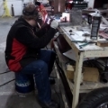
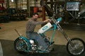
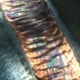
Ok. I weld on cast aluminum at least once a week, and about every other week or so I come across a very tight spot in a casting that needs to be welded, that requires about a 1 inch long stickout or longer, and they always give me fits. Here is a picture of what I'm talking about. It's always the same problems, either porosity from not enough shielding or turbulence from too much shielding. I've adjusted from 20 all the way up to 30 cfh and I cant find a sweet spot. Here are my parameters:
Miller Diversion 180
AC High Frequency Inverter
125 amps
75% Helium / 25% Argon
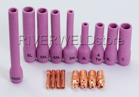
#17 Air Cooled Tig Torch
# 7 Stubby GAs Lense
3/32 Pure Green Tungsten Electrode with a rounded ball end
As far as technique I'm using a "move forward and give it some rod" dab and fill stitching motion. I dont think its just a bad batch of cast aluminum because the rest of the crack that I could access welded just fine. I think I'm just using a bad technique or an improper setup.
Can anyone help me out? What do you guys do/use to tig weld tight and hard to reach spots that require long stick outs?
I wonder if the shielding issues stem from the high He mix. Since He is less dense than air, it won't blanket an area the way Ar will. But I realize you probably need the He on that heavy casting. A challenging situation for sure.
I actually get my best results in tight spots like that with a -20 torch with small consumables, standard collet body, and #4 cup. Greatly shortens the stickout on a weld like that. Better, if closer, coverage, and long post-flow.
In a really tight space, I have a #4 cup I've cut down to "just" past the end of the collet. With a short back-cap, this reduces the head of my -20 torch to about 1 1/4".
I personally would try to make a purge dam out of foil or something to trap the cover gas in the weld area. I've also gone back to a regular collet body for Aluminum and have had less issues with gas coverage, I know that seem counter- intuitive, but it works. You can use a long stick out with a regular collet body if the tungsten is still enveloped in the gas being held there from the purge dam. I've seen our everyday pipe welders do a repair on a root pass through a root gap on the opposite side of a 4" Inconel pipe with a 6" stick out. The back purge on the pipe keeps the tungsten happy.
As Zank has touched on, that's a high Helium to Argon mix and will rise out of the weld zone very quickly and needs to be trapped. Anything you can do to keep the gas in the area is going to help you here. You're paying big money for Helium and it's working against you if it doesn't stay in the weld zone. I also would cut the gas flow back instead of raising it, if you're running at too high of a flow rate you run the risk of pulling in atmosphere in a vortex that's way heavier than your Helium/Argon mix.
I know a lot of what I just said goes against what the swimming pool size gas lens salesmen are telling everyone, but give it a try, you might be pleasantly surprised.
castweldsolutions wrote:Ok. I weld on cast aluminum at least once a week, and about every other week or so I come across a very tight spot in a casting that needs to be welded, that requires about a 1 inch long stickout or longer, and they always give me fits. Here is a picture of what I'm talking about. It's always the same problems, either porosity from not enough shielding or turbulence from too much shielding. I've adjusted from 20 all the way up to 30 cfh and I cant find a sweet spot. Here are my parameters:
Miller Diversion 180
AC High Frequency Inverter
125 amps
75% Helium / 25% Argon
#17 Air Cooled Tig Torch
# 7 Stubby GAs Lense 3/32 Pure Green Tungsten Electrode with a rounded ball end
....and the balled pure is used instead of Lan. sharpened.....becuz?
Miller recco's using sharpened, Lan. or Cer. electrodes for inverters.
The 180 has a fixed AC balance--but this still should help to create a focused
arc vs. one that spreads out and dances around......makes all the difference in
AL cavity welding.
@anders,
That's why I suggested lowering the flow rate to cause less turbulence in the gas so it doesn't draw in atmosphere. The cavity causes an eddy of sorts which causes the gas to change directions just in time to be hit with more incoming gas and a vortex is created.
The Helium being the lightest gas in the equation now makes up the majority of the atmosphere in the gas envelope and will carry the ionized Argon as it's trying to rise away from the weld zone leaving air to be the heavier gas now. There's the reason I suggested some sort of purge dam to keep air at bay and keep the weld zone purged.
Not sure if I'm explaining this to where it makes sense.
Now maybe someone can explain to me how a balanced AC arc has any different effect on a tungsten coming from a transformer than it does coming from an inverter. Does an inverter make some kind of different electricity that I'm not aware of? I've used Thoriated tungsten for years to weld Aluminum because I didn't care for the ball on pure and would rather deal with the little split up end. So if you can't change the balance on the machine what makes the weld current different from a transformer, anybody know?
In order to create a pocket you could lay (or use heat tape) a plate across the end to help trap the shielding gas. Of course this may also hinder your access. In some cases this can be effective.
This is what I believe Len was referring to when he wrote about building a purge dam.
Braehill wrote:@anders,. So if you can't change the balance on the machine what makes the weld current different from a transformer, anybody know?
Len
Perhaps a sales person could explain(SAID ,TONGUE IN CHEEK! ) )
Everlast 250EX
Miller 250 syncrowave
Sharp LMV Vertical Mill
Takisawa TSL-800-D Lathe
Coupla Bandsaws,Grinders,surface grinder,tool/cutter grinder
and more stuff than I deserve(Thanks Significant Other)
In my experience with cast aluminum, or any trapped corner for that matter, the shielding gas does not want to flow into a dead end like that so, I drill it through if I can, and create a chimney path, either through, or up and out, with a series of side by drill holes or a thru-groove. Lowering the flow rate can help.
Think about trying to squirt water into a glass all of a sudden like and most of it will come back at you, for lack of a better explanation.
Drill the entire crack out with a 1/8 drill bit so that your shield gas and heat can flow thru. Start at the bottom where it's trapped, and work your way up and out of that cavity.
Miller ABP 330, Syncrowave 250, Dynasty 300 DX.
Honorary member of the Fraternity of Faded Tee Shirts.
Thanks a bunch for all the advice fellas! It's a wealth of knowledge and I'm taking it all in. I'm going to see if I can do some experiments with some of the tips ya'll have given and if I can I'll post the results down the road.
Braehill, I've already tig welded some beads on aluminum last night with a traditional set up vs a gas lens setup and I was surprised at the difference of the appearance of my welds. They did look better using a traditional collet body and nozzle instead of a gas lens.
To answer why I use pure green tungsten, honestly, because that's what I read out of the books I teach out of, and its what the school supplies. Out of the three books my school has taught out of over the years, every one of them recommends pure green or zirconiated electrodes for aluminum tig welding. I'm still learning to apply "street smarts" with "book smarts" so to speak. While I'm an instructor, my "major" was with stick and flux core, and I never had any formal training on tig. So when it comes to tig welding, I've only learned by what I've studied, what I've seen from Jody's videos, and now this forum.
I love this skill, and even more so that I never stop learning about it. This forum rocks!
My inverter's manual says not to use pure tungsten.
I use 2% Lanthanated sharpened to a point for about everything.
The starts are real crisp with the pointed electrode. On old dirty
aluminum requiring a bit more cleaning action I blunt the point a bit
since the added cleaning action tends to burn the tip back a bit anyways.
AFAIK for inverters the advice not to use 'pure'/green electrodes but instead use zirconiated or ceriated ones for A/C stems from the issue that pure tungsten carries current less easily than alloyed tungsten types and an inverter tries to put out a square-wave A/C as much as possible where the current 'rush' each time the polarity switches is much bigger than with a transformer sine-wave which gradually drop to 0 and build up again on the other side.
As such the use of green/pure electrodes on an inverter can make the resulting A/C waveform applied to the workpiece resemble more of a sine-wave because of the resistance in the electrode even though the welding machine is generating as much of a square-wave as possible.
That may lose some of the 'crispness' of the weld arc on inverter machines and may even mess up (or basically smooth out/dampen) additional high-frequency pulse settings if used making then ineffective.
Using green electrodes on an inverter with A/C won't (or should not ) break anything, it just means it may not allow the usage of all inverter based features when needed or they work less well than expected.
Everlast 250EX
Miller 250 syncrowave
Sharp LMV Vertical Mill
Takisawa TSL-800-D Lathe
Coupla Bandsaws,Grinders,surface grinder,tool/cutter grinder
and more stuff than I deserve(Thanks Significant Other)
@Arno,
That's the reason I love this forum, if you don't know the answer you can throw it out here and somebody comes back with an answer and we all become a little smarter. Good stuff. Thanks.
Arno, that makes sense. The sharp transition of a square wave might even lead to tungsten deposition in the weld, when the current sharply/instantly changes from EP to EN.
I did a little experimenting and thought I'd share the results.
I didn't use any cleaner or soak, just a die grinder with a sanding disk and then a stainless steel brush. The metal is a cast aluminum piece cut out of a broken jeep bell housing. Each bead was welded with a 3/32nd, 2% lanthanated tungsten (man I should have switched to this a LONG time ago ), at 15 CFH for the gas shielding, using 100 amps, on a Miller Diversion 180. After welding each bead, the plate was air cooled back to where it could be held with a bare hand. I got the most soot when I welded with the gas lens setup (Does this mean it pulled out more oxides or anything?). The beads wetted in pretty much the same with both the ceramic nozzle and the gas lens. The beads run on 100% argon were narrower with a higher crown while the beads with the helium mix were almost twice as wide and almost half as high. The 100% argon actually SOUNDED smoother, but the puddle was dull with lots of black oxides. The 75% helium sounded much rougher with a lot more "crackling", but it puddled immediately & SUPER SHINY with barely any oxides visible in the puddle.
After doing this, I do like using a traditional setup on aluminum vs a gas lens, and I'm not entirely sure I really need the helium, at least not 75%, and I think I could get the same benefit with a lot less, probably 50% to 25% Helium instead.
I am late to the party once again but I believe I can add to this conversation. The first question I have to ask it your torch angle? Areally you straight on to 10° or more of a 45°? The 45° will not help you especially if you are running a lot of gas flow.
I am experienced with cast alum and the nasty looks is quite common, depending on what the cast material is. I have welded some that goes very nice and some not so much. On the He, I see absolutely no reason to use it on cast alum, unless you feel you need it for thicker members. I have a Division 180 as well and it will weld just fine for what you are trying to do.
I a recent convert back to conventional collet body setup for welding alum and have been performing tests just like you just did and concluded the gas lens is not necessary and can actually make it worse in some cases.
One trick I will offer is depending on what the weld is, I will run a bead and grind it almost entirely back out so I have a good foundation to weld on. You and I do quite a bit of cast iron and cast alum repairs and I will help in anyway I can.
-Jonathan