Tig welding tips, questions, equipment, applications, instructions, techniques, tig welding machines, troubleshooting tig welding process
- jumpinjackflash
-
Guide

-
Posts:
-
Joined:Sun Feb 02, 2014 6:14 pm
-
Location:Near Mt Airy
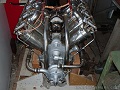
This is a strut attachment point on a 5/8 by .035 fuselage tube. The ones that were built back in the early 80s were mig welded and I'm not doing that if possible. Just wanted to know if there is any advice to get this welded up from the inside of those cross tubes with a TIG torch and do it in a safe manner. This is a picture of my other project that's finished this is on a new project. thanks in advance for any tips on how to get in here and weld this to the plate without killing it !!! Guess I'll have to light up on the .080 plate and sneak up to the 5/8 tube.
- Attachments
-
- IMG_20191121_163444080_HDR.jpg (42.55 KiB) Viewed 2560 times
-
- IMG_20200127_173752460.jpg (25.26 KiB) Viewed 2560 times
Building an airplane is at times somewhat like a divorce.....with the exception that she doesn't leave
J.J. Flash
J.J. Flash

Not really understanding the joint configuration? Not that i could give you reliable advice on welding airplanes. As i have never welded anything that critical in my life.
More curious than anything
Sent from my SM-G930V using Tapatalk
More curious than anything
Sent from my SM-G930V using Tapatalk
Without sounding like a patronizing arsehat... if you have to ask, this is not something you should weld. Simply because lives will depend upon your work. Maybe it’s only your life, but if that plane comes out of the sky where it lands could involve others. Many others.
But since you asked, I’ll answer the question as best I can:
The heat and strength of that weld always is controlled by the thinner material. 0.035 will use far less heat than 0.080 material so the penetration into the 0.080 will be poor. And reaching into a “fillet” type weld where a round surface intersects a flat surface always, always creates a weak weldment. You get this which is why you asked.
To reach in, I use either of two approaches: a large cup (#12 or >) and lots of argon, long stick out and try to get as tight an arc with the best shielding. OR, I go in the reverse. I use a small, long-nosed snout #4 with less argon (5-6cfh) and tuck the cup in there. With this approach, I use a smaller CFH because I find the turbulence in that joint type can be problematic where coverage area is sufficient. Thin gauge filler, control the heat, and stitch it.
Others may have different ideas and recommendations. And you’re welcome to tell me to bugger off with the cautionary preamble. Fair play on that. Just offering friendly advice.
- jumpinjackflash
-
Guide
-
Posts:
-
Joined:Sun Feb 02, 2014 6:14 pm
-
Location:Near Mt Airy
No issues with anyone , no one being an arsehat... I do fly what I weld. I have no issues with that or making a sound weld. If you only knew what level of work that was signed off and flies over many heads at night.... Let's just say I have trust in my work. I was simply looking for some tips on "getting in there" if you know what i mean. Probably going to change bottom round tube, load bearing member , out to 4130 square tube. Better weld produced but that tubing is $13 / ft ! Rather have best weldment I can get. Suggested by EAA group.
Building an airplane is at times somewhat like a divorce.....with the exception that she doesn't leave
J.J. Flash
J.J. Flash
I believe there are aviation standards for light aircraft in the USA and specified weldment procedures for all types of frame joints to go with it.
These procedures can call up extra plug welds or reinforcement, for example, that we on the forum could not conceivably think of.
My advice is to get a hold of that manual and do what the relevant procedure says.
Don't worry about what others might be getting away with, worry about getting your own work done right.
Flat out like a lizard drinkin'


I don't quite understand what you are asking, are you trying to figure out how to get your torch into a tight spot or the best weld configuration, bracing pattern or what is it?
I'm curious as well but I don't understand the question you have.
I'm curious as well but I don't understand the question you have.
if there's a welder, there's a way
- jumpinjackflash
-
Guide
-
Posts:
-
Joined:Sun Feb 02, 2014 6:14 pm
-
Location:Near Mt Airy
Just wanted to see how others would take on the task...nothing more. This is my fourth aircraft from plans...not new to building solid planes. I have 4 engineers opinions and the local EAA chapter with me. I don't negatively impact others...hmmm. This place used to full of helpful ideas...
Guess things change.
Have fun
Guess things change.
Have fun
Building an airplane is at times somewhat like a divorce.....with the exception that she doesn't leave
J.J. Flash
J.J. Flash
Not sure if you are responding to me.jumpinjackflash wrote:Just wanted to see how others would take on the task...nothing more. This is my fourth aircraft from plans...not new to building solid planes. I have 4 engineers opinions and the local EAA chapter with me. I don't negatively impact others...hmmm. This place used to full of helpful ideas...
Guess things change.
Have fun
I'm trying to help, I just don't get what you are asking.
Are you trying to get into a tight spot?
if there's a welder, there's a way
I asked if you could explain the joint a bit so i could understand it a bit better. Maybe an idea would pop into my mind. Not sure why you are offended? It seems all the responses where helpful in nature with a heavy dose of caution. You might feel irritated because you feel comfortable flying in a box you welded, but try to understand many of us don't know 4 aviation engineers, and have never welded an airplane. I think the caution is more out of respect for the profession of welding and not from an unwillingness to help.jumpinjackflash wrote:Just wanted to see how others would take on the task...nothing more. This is my fourth aircraft from plans...not new to building solid planes. I have 4 engineers opinions and the local EAA chapter with me. I don't negatively impact others...hmmm. This place used to full of helpful ideas...
Guess things change.
Have fun
Cheers
Sent from my SM-G930V using Tapatalk
I’d use a Furick cup, like the BBJ, long stick out and lots of argon, like cj737 suggested. You might also consider building a couple dams around the joint to hold the argon in there as you weld it. From a practical standpoint, it doesn’t look like a very good joint design. Given that it’s on the plans, you are pretty much stuck with it. All your flight loads will be from your struts to the cross tube, so that would be the critical welds, either side of the cross tube. The joint to your lower longeron isn’t near as critical, but it looks like the tab below likely goes to your landing gear, so loads from the gear will transfer to the longeron and the rest of the structure more in compression than in tension.
Sent from my iPad using Tapatalk
Sent from my iPad using Tapatalk
David
Everlast 210 EXT
Lincoln AC225
Lotos LTP5000D
Oxy-Acetylene
Everlast 210 EXT
Lincoln AC225
Lotos LTP5000D
Oxy-Acetylene
- MinnesotaDave
-
Weldmonger

-
Posts:
-
Joined:Sun Oct 27, 2013 10:57 pm
-
Location:Big Lake/Monticello MN, U.S.A.
If I read your drawing correctly, that's a really awful joint configuration to weld.
Any chance of a gradual flattening of the round tube to make it easier to weld?
Plus, the side-to-side rigidity of that configuration is quite poor (rocking motion). The welds are close together and result in the tube having a good deal of torque to work with to crack the tube at the toes of the weld.
If no flattening is allowed, laying in a piece of appropriately sized round bar moves the weld out farther and is easier to weld (in my opinion).
It results in 2 extra welds, but this isn't a production type part so that extra time wouldn't matter.
Dave J.
Beware of false knowledge; it is more dangerous than ignorance. ~George Bernard Shaw~
Syncro 350
Invertec v250-s
Thermal Arc 161 and 300
MM210
Dialarc
Tried being normal once, didn't take....I think it was a Tuesday.
Beware of false knowledge; it is more dangerous than ignorance. ~George Bernard Shaw~
Syncro 350
Invertec v250-s
Thermal Arc 161 and 300
MM210
Dialarc
Tried being normal once, didn't take....I think it was a Tuesday.
I agree it is a very poor joint design, however in aviation weight is everything (even a few oz.) in the OPs project, it is an ultralight aircraft. The primary loads for the joint aren’t with the tube perpendicular to the plate, but the one behind it that goes lengthwise, and crosses to the other side of the airplane with another fitting in reverse on the other side. The wing struts bolt to these fittings.MinnesotaDave wrote:If I read your drawing correctly, that's a really awful joint configuration to weld.
Any chance of a gradual flattening of the round tube to make it easier to weld?
Plus, the side-to-side rigidity of that configuration is quite poor (rocking motion). The welds are close together and result in the tube having a good deal of torque to work with to crack the tube at the toes of the weld.
If no flattening is allowed, laying in a piece of appropriately sized round bar moves the weld out farther and is easier to weld (in my opinion).
It results in 2 extra welds, but this isn't a production type part so that extra time wouldn't matter.
A much better design would be to have a finger that wraps this cross tube and then it is a simple lap joint with the cross tube.
Sent from my iPhone using Tapatalk
David
Everlast 210 EXT
Lincoln AC225
Lotos LTP5000D
Oxy-Acetylene
Everlast 210 EXT
Lincoln AC225
Lotos LTP5000D
Oxy-Acetylene
- jumpinjackflash
-
Guide
-
Posts:
-
Joined:Sun Feb 02, 2014 6:14 pm
-
Location:Near Mt Airy
DGA pilot gets it spot on. Save but the full volkswagon power plant. The consensus is to put a .625" x . 065 wall CroMo square tube for load bearing member in tension. That will make a better weld at that junction. FEA shows almost 3 times strength needed for loads at max flight loads. Thanks to a friend that used to work in aviation design that has been a great help with all the computer work. Another friend in the chapter has tabs similar to this on his pitts model 14 he's building, but has a pair of formed .063 plates fusion welded edges where the lift cables tie into and tied to the tube structure with finger tabs outward onto the tubing. They form a "Y" where they are welded to the tubes in tension. I understand the caution....that's why I want to make this the best that can be done within reason. Taking in all the info I can get my mind on. Since it is experimental light sport category changes for the better are a good thing. They have also toyed with the idea of making part of this structure before welding in the lower longerons...Just to have better access to weld.
Trust me on being cautious I got a few good years left in me and I plan to enjoy them plus I've got some other airplanes want to get built
Trust me on being cautious I got a few good years left in me and I plan to enjoy them plus I've got some other airplanes want to get built
Building an airplane is at times somewhat like a divorce.....with the exception that she doesn't leave
J.J. Flash
J.J. Flash
http://cloud.tapatalk.com/s/5e4beb68539ae/12509.PDF
If you look at figure 12 on this drawing, you can see how a similar fitting design was done by Piper for the PA-20. Much better joint design, and likely lighter than the one in your plans.
Sent from my iPad using Tapatalk
If you look at figure 12 on this drawing, you can see how a similar fitting design was done by Piper for the PA-20. Much better joint design, and likely lighter than the one in your plans.
Sent from my iPad using Tapatalk
David
Everlast 210 EXT
Lincoln AC225
Lotos LTP5000D
Oxy-Acetylene
Everlast 210 EXT
Lincoln AC225
Lotos LTP5000D
Oxy-Acetylene
http://cloud.tapatalk.com/s/5e4bea499f055/12509.PDF
Look at figure 12 on this drawing. Much better design and likely lighter.
Sent from my iPad using Tapatalk
Look at figure 12 on this drawing. Much better design and likely lighter.
Sent from my iPad using Tapatalk
David
Everlast 210 EXT
Lincoln AC225
Lotos LTP5000D
Oxy-Acetylene
Everlast 210 EXT
Lincoln AC225
Lotos LTP5000D
Oxy-Acetylene
Return to “Tig Welding - Tig Welding Aluminum - Tig Welding Techniques - Aluminum Tig Welding”
Jump to
- Introductions & How to Use the Forum
- ↳ Welcome!
- ↳ Member Introductions
- ↳ How to Use the Forum
- ↳ Moderator Applications
- Welding Discussion
- ↳ Metal Cutting
- ↳ Tig Welding - Tig Welding Aluminum - Tig Welding Techniques - Aluminum Tig Welding
- ↳ Mig and Flux Core - gas metal arc welding & flux cored arc welding
- ↳ Stick Welding/Arc Welding - Shielded Metal Arc Welding
- ↳ Welding Forum General Shop Talk
- ↳ Welding Certification - Stick/Arc Welding, Tig Welding, Mig Welding Certification tests - Welding Tests of all kinds
- ↳ Welding Projects - Welding project Ideas - Welding project plans
- ↳ Product Reviews
- ↳ Fuel Gas Heating
- Welding Tips & Tricks
- ↳ Video Discussion
- ↳ Wish List
- Announcements & Feedback
- ↳ Forum News
- ↳ Suggestions, Feedback and Support
- Welding Marketplace
- ↳ Welding Jobs - Industrial Welding Jobs - Pipe Welding Jobs - Tig Welding Jobs
- ↳ Classifieds - Buy, Sell, Trade Used Welding Equipment
- Welding Resources
- ↳ Tradeshows, Seminars and Events
- ↳ The Welding Library
- ↳ Education Opportunities