Tig welding tips, questions, equipment, applications, instructions, techniques, tig welding machines, troubleshooting tig welding process
Kodokan
  • Posts:
  • Joined:
    Thu Nov 04, 2021 2:05 am

Tried pie cuts on Saturday.

Image

Image

Image
cj737
  • Posts:
  • Joined:
    Thu Sep 29, 2016 8:59 am

You may notice your arc wandering and sputtering whenever you have a magnet nearby. Try to only tack with it around, then move it and weld. Saves the magnet and helps the arc remain stable.
Kodokan
  • Posts:
  • Joined:
    Thu Nov 04, 2021 2:05 am

My little folding welding table. Not much more than a glorified TV tray. Very happy with it, so far. Hopefully, soon I'll make room in the garage to keep it set up. Raining today, so I can't weld.

Image

First time welding aluminum on the home TIG. Trying different stuff. Guess it'll take some time to get dialed in.

Image

Pics from last week. Thursday is aluminum day. I did more than this, but some stuff goes straight into the waste bin.

Image

3 of these 4 outside corner beads were not bad. 2 of the beads are good enough to go on any of my custom bikes. The other 20 or more beads I laid down definitely don't make the cut.

Image

If I can get to the point where I can consistently make good looking beads, I'll start looking at the penetration and quality.
Kodokan
  • Posts:
  • Joined:
    Thu Nov 04, 2021 2:05 am

On the topic of penetration- the problem is, I don't know what it should look like. I know what the school wants my practice beads to look like, but not sure about real world fabrication.

For tubes that flow gas or liquid, it makes sense that the inside of the tube should be smooth. In other words- zero penetration beyond the thickness of the metal. Not sure what the pro fabricators do.

For now, I'll keep working on acceptable-looking beads. No matter how strong the bead is, I won't be happy if it looks like crap.

Image
Kodokan
  • Posts:
  • Joined:
    Thu Nov 04, 2021 2:05 am

Tried TIG brazing a pie cut with SiBr.

Didn't come out well, but seems like a very strong bond.

Image
Kodokan
  • Posts:
  • Joined:
    Thu Nov 04, 2021 2:05 am

At school, there's a table where we put our finished projects for grading by the instructor.

Last time I passed by the table, I saw this....

Image

Maybe I'm not doing so bad.
Kodokan
  • Posts:
  • Joined:
    Thu Nov 04, 2021 2:05 am

Got all my shit together and went to class... only to find a closed campus.

Ceasar Chavez day. Great idea for the Mexican immigrants- Close the schools for another day so people can party with alcohol and overeat.

So, got some more work done on my mini purge box.

Sliced in the vent slots with a dremel.

Image

Used a triangle file to flare the slots. Next will be a test to check the gas flow.
I could connect gas tubes to both sides of the tube, but I would prefer to use only the right side. Will save table space, and stay out of the way of my left hand.

Image
Kodokan
  • Posts:
  • Joined:
    Thu Nov 04, 2021 2:05 am

Forgot to post the first pic of the mini purge box.

Image
tweake
  • Posts:
  • Joined:
    Mon Dec 18, 2017 4:53 am
  • Location:
    New Zealand

thats pretty cool. :P :mrgreen:
tweak it until it breaks
Kodokan
  • Posts:
  • Joined:
    Thu Nov 04, 2021 2:05 am

Well, it wasn't a great night at Moto Welding School, but progress was made.

I got stuff ready for bubble testing the mini purge. I cut down the vent tubing, plugged one end, and smoothed out the ends with a file. The holes/slots in the tube increase in size from proximal to distal, which I thought would help even out the gas distribution. Found a water bottle large enough for the tube, and made a plan.

I know that water pressure (even the small amount in the bottle) is considerably more than ambient air pressure. So, I figured it might not work, or could take more argon flow pressure to get results. First plan is vertical bubble, second plan is horizontal bubble, third is smoke test. Whatever works.

Couldn't get a good pic, I guess because of the bottle shape. You can definitely see lots of bubbles at the top. I could see clearly in person.

Image

In order to get bubbling out of the distal vent, I had to crank up the argon to 60cfh. So, the test worked, but the results suck.

For the horizontal bubble test, I dumped half the water and layed the bottle on its side. Was able to get bubbling from the distal vent at 20cfh.

My guess is that the vent tube will work okay in ambient air, using normal argon pressure. I'll purge the box for a minute or two over 20cfh before use. Will also figure out a removable cap for the distal end of the tube so I can remove it momentarily when purging to get argon past the distal vent.

I'll skip the smoke test. Was going to put smoke only into the bottle to evaluate the vents.

Bad news is, I forgot to bring the box home. I was going to draw the welding plate tonight and give the drawing to the instructor tomorrow. He said he might be able to get it made at his (other) job. Might be able to draw it tomorrow at class, but I hate to reduce my TIG time.

I think my project tomorrow will be a 1/8" aluminum cube. Did some aluminum welding tonight, but took forever to get the testing done.
cj737
  • Posts:
  • Joined:
    Thu Sep 29, 2016 8:59 am

You don’t want nearly those levels of pressure for purging. And all the vent tubes I’ve ever seen have equally drilled holes. Argon is heavier than air so it will displace the air without requirement of “equal flow” along the tube.

When I purge, I run about 3cfh, nary a bit more.
Kodokan
  • Posts:
  • Joined:
    Thu Nov 04, 2021 2:05 am

Three inch cube, using 1/8" aluminum, from yesterday.

Will post some close-ups of the welding, and what I learned, later tonight.

Image
Kodokan
  • Posts:
  • Joined:
    Thu Nov 04, 2021 2:05 am

First problem welding the aluminum cube was, I didn't have good tools for setup. I put the aluminum against a magnet with steel bars on the outside. Didn't hold well.

My first couple of beads had a depression on each dime. Was trying different movements to fix it, but just had to slow down a little.

Image

Some of the beads aren't on a 45 degree angle. Have to work on that next time. In the first pic I posted of the whole box, this is the reason the bottom weld isn't visible.

Image

The fit-up wasn't ideal, so I had to use filler rod on a couple of beads. They don't look as good. Need to practice more.

Image
Kodokan
  • Posts:
  • Joined:
    Thu Nov 04, 2021 2:05 am

Should have said this about the cube:

1/8" Aluminum coupons from weldmetalsonline
1/16" 4043 filler rod
1/16" 2% Lanthanated
Gas Lens with #8 cup
120 Amps
15 cfh Argon

What I used. Not a recommendation.
tweake
  • Posts:
  • Joined:
    Mon Dec 18, 2017 4:53 am
  • Location:
    New Zealand

Kodokan wrote: Mon Apr 04, 2022 4:09 am Should have said this about the cube:

1/8" Aluminum coupons from weldmetalsonline
1/16" 4043 filler rod
1/16" 2% Lanthanated
Gas Lens with #8 cup
120 Amps
15 cfh Argon

What I used. Not a recommendation.
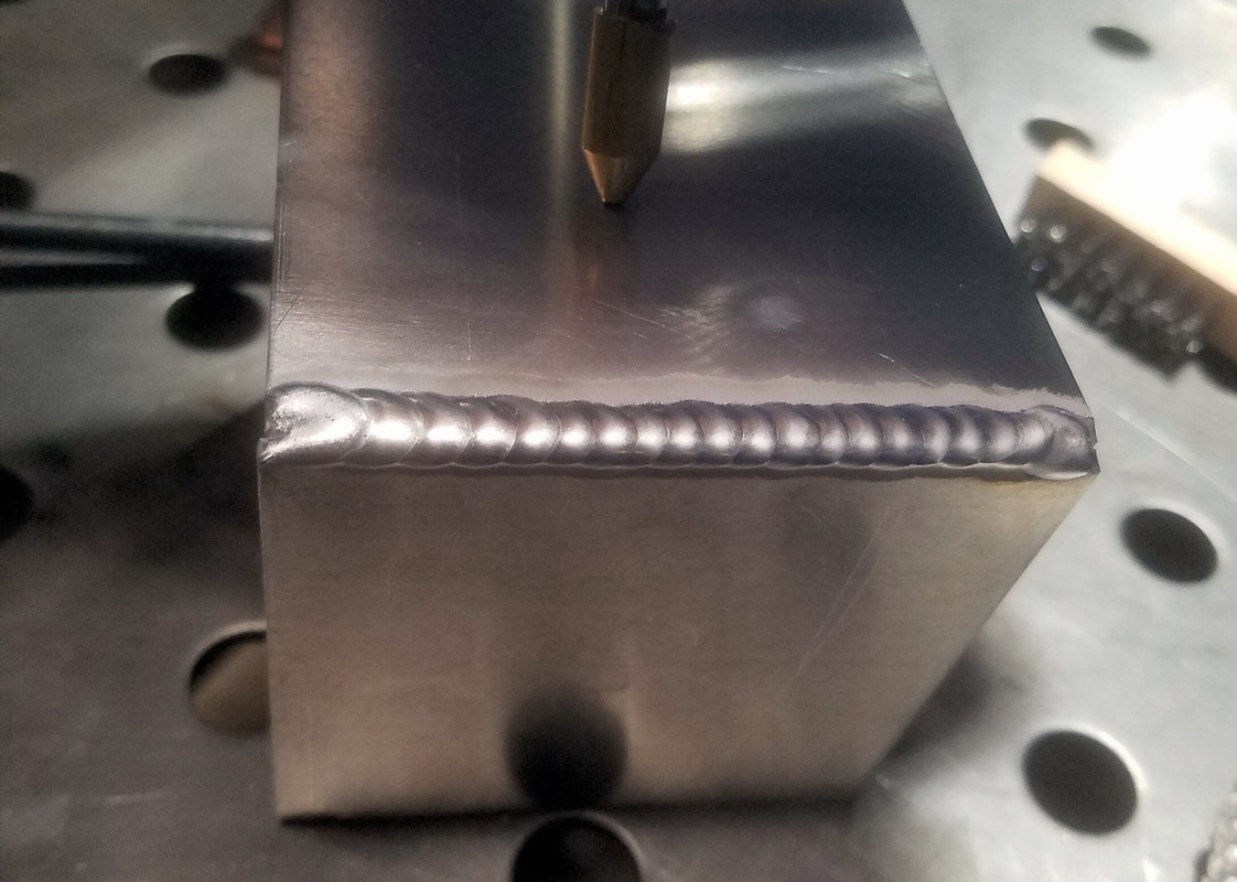
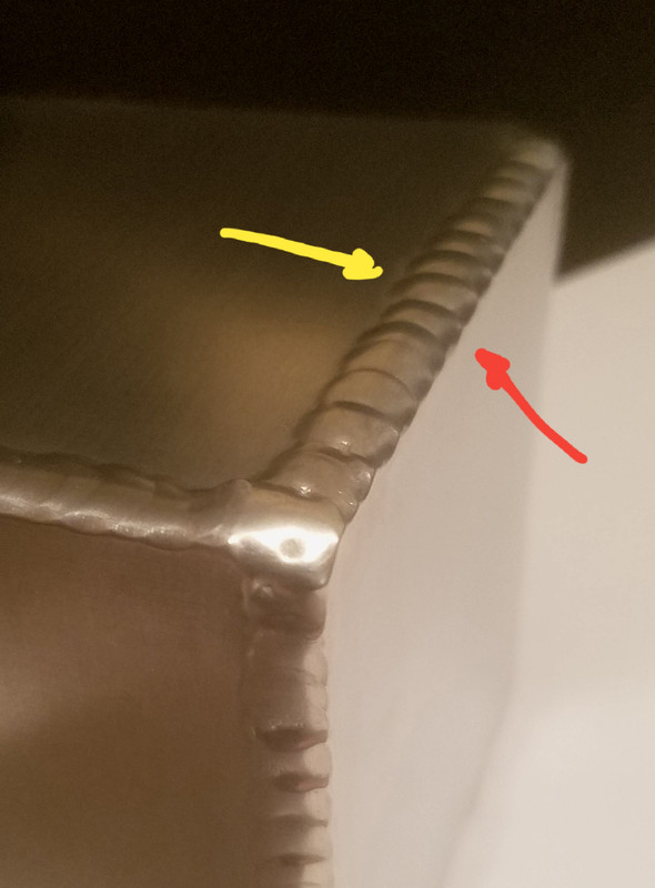
yeah its noticeable with the cold tack on tack.
amps to low, filler to small, tungsten to small.
amps up around 150 or so (it will vary depending on other settings, plus use of pedal), 3/32 filler and 3/32 tungsten. also try a 5 cup.
start hot, slam the pedal. get it to flow down into the joint. back off the amps if things start getting to hot and puddle is getting out of control.
you need to use filler most of the time with aluminium, afaik there is only one type that will weld properly without filler.

your setup would be fine for steel, but aluminum tends to be the opposite of everything you have learnt with steel.
eg pulling filler out of the gas flow is recommended with aluminum.
lack of amps is the common problem and makes people go slow, which then causes overheating. need to keep the amps up and keep the travel speed up.
tweak it until it breaks
Kodokan
  • Posts:
  • Joined:
    Thu Nov 04, 2021 2:05 am

After looking at the aluminum cube some more, I realized that on the beads I did with no filler- one side (yellow) is convex, and one side is concave (red). All of them have this characteristic. So, need to work on my filler rod technique, and use it. (Like tweake said.)

Image

Now that I've had a little experience with my home TIG, I can already notice a big difference between a $5,000 TIG, and a $15,000 TIG (at school). The Miller Dynasty 400 just works better.
Kodokan
  • Posts:
  • Joined:
    Thu Nov 04, 2021 2:05 am

Wanted to try some coping welds. Got this steel tubing because it's close to the thickness of the RZ350 steel frame.

Not at all happy with the appearance, but seems like a strong weld. I think the penetration is good. No holes or gaps, so I'm okay with this first try.

Looks like a bicycle head tube & top rail.

Image

Image

Image
cj737
  • Posts:
  • Joined:
    Thu Sep 29, 2016 8:59 am

Kokodan - when you weld up tubing at both ends, drill a small vent hole in the intersecting tube beneath the coping or along the length of the tube. The heat and gas from welding needs a place to vacate else you can find your closing bead blowing out from internal pressure.

While not at all necessary, some higher end frame builders still purge their steel frames. It’s cheap insurance for a “best case” weld.
Kodokan
  • Posts:
  • Joined:
    Thu Nov 04, 2021 2:05 am

cj737 wrote: Sun Apr 10, 2022 6:36 pm Kokodan - when you weld up tubing at both ends, drill a small vent hole in the intersecting tube beneath the coping or along the length of the tube. The heat and gas from welding needs a place to vacate else you can find your closing bead blowing out from internal pressure.
I can weld up the drilled hole after it cools?

Okay to leave the last bit of weld open until it cools, then go back and finish (instead of drilling a hole)?

Thanks! I don't need more injuries.
Kodokan
  • Posts:
  • Joined:
    Thu Nov 04, 2021 2:05 am

More progress on the mini purge.

Added 2 aluminum cooling plates, each 3/8" thick.

Image

I might remove the crossbars below the vent, depending on the argon flow. Will probably do a smoke test and see what it looks like.

Image
cj737
  • Posts:
  • Joined:
    Thu Sep 29, 2016 8:59 am

Kodokan wrote: Mon Apr 11, 2022 4:30 pm
cj737 wrote: Sun Apr 10, 2022 6:36 pm Kokodan - when you weld up tubing at both ends, drill a small vent hole in the intersecting tube beneath the coping or along the length of the tube. The heat and gas from welding needs a place to vacate else you can find your closing bead blowing out from internal pressure.
I can weld up the drilled hole after it cools?

Okay to leave the last bit of weld open until it cools, then go back and finish (instead of drilling a hole)?

Thanks! I don't need more injuries.
Yep. And yup. Whichever you prefer.
tweake
  • Posts:
  • Joined:
    Mon Dec 18, 2017 4:53 am
  • Location:
    New Zealand

Kodokan wrote: Mon Apr 11, 2022 4:30 pm
cj737 wrote: Sun Apr 10, 2022 6:36 pm Kokodan - when you weld up tubing at both ends, drill a small vent hole in the intersecting tube beneath the coping or along the length of the tube. The heat and gas from welding needs a place to vacate else you can find your closing bead blowing out from internal pressure.
I can weld up the drilled hole after it cools?

Okay to leave the last bit of weld open until it cools, then go back and finish (instead of drilling a hole)?

Thanks! I don't need more injuries.
yes sort of. kinda depends on the situation. if the weld has a good fit up then the gap may be far to small to vent the air. plus as you weld along, the heat gets higher and the gap gets smaller, making the air speed go up so you can have quite a fast bit of air coming out right at your weld puddle.
so often its easier to put a hole in and in an easy place to weld or somewhere where its easy to hide.
tweak it until it breaks
Kodokan
  • Posts:
  • Joined:
    Thu Nov 04, 2021 2:05 am

Thanks, tweake. I wasn't thinking about the fit-up.

TIG Brazing Rod Shootout.

This is ERCuSi-A. Sizes are 1/6", 0.045", and 0.035". Steel plate is 1/16".
2% Lanthanated 1/16". #8 cup with gas lens. 50 amps. Dropped to 40 amps with 0.035 rod, 50 seemed too hot. 15cfh argon.

1/16"
Image

0.045"
Image

0.035"
Image

A good welder could probably do just as well with any of the 3 rods. For a beginner like me, looks like size matters.
Kodokan
  • Posts:
  • Joined:
    Thu Nov 04, 2021 2:05 am

Here's how the purge box is sealed.

First, I fold a piece of heavy duty aluminum foil, so it's 2 layers thick. Then, I set the welding plate on top and trace around the outside and the hole with a black marker. Then cut the hole with a scissors (a little larger than the markings).

The grate drops in the tray, with an aluminum plate on top. Then the foil, and the aluminum top plate.

Image

I trim off the extra foil, leaving about 3/4" to wrap around the tray lip.

Image

I sealed around the vent tube on the inside of the tray with high-temp silicone. It keeps the tube in place, and in the proper orientation. I also got a high-temp silicone plug for the end of the vent tube. I remove the plug momentarily when purging the tray to remove the last bit of air from the tube.

I leave a small gap open on the top plate to purge air and excess argon.
Kodokan
  • Posts:
  • Joined:
    Thu Nov 04, 2021 2:05 am

Stainless Test.

Setup like this. I left a small opening on the right side of the stainless coupons.

Image

Top is with no purge Argon, bottom is with purge Argon.

Front:
Image

Back:
Image

Image

Looks like the mini purge box is working.
Post Reply