I was charged with welding 4140 to A572 Gr B and would like to pick your brain. The 4140 is 12" bar approx 38.75" long and the A572 is 3" thick with 2" gussets. This piece will see 1.2 million lbs of force in both directions and was VERY, VERY expensive to make. The prints show "preheat sufficient for material thickness, Filler for base material, slow cool" or something like that.
No specific WPS provided but I "borrowed" some from someone else to use as a guideline. From what I can see the recommended filler is ER70S-6 or E7018 with a preheat of 400-700 deg F. So I calculated the CE and came up with .77-.80 approx depending on the values one inputs, which puts me in the 600-700 deg F range. I have ran this through several friends, most of which are CWI's and the general answer is pre-heat to 400 min and keep interpass at 700 with a 50 deg F a hour cool off rate.
My experience with 4140 is small parts that have never seen this kind of loading before. I am not nervous to tackle this project but want all the help I can get. Anyone want to chime in with thoughts or experiences?
-Jonathan
mig and flux core tips and techniques, equipment, filler metal
- Superiorwelding
-
Weldmonger

-
Posts:
-
Joined:Thu Jan 24, 2013 10:13 pm
-
Location:Eddy, TX
- Attachments
-
- Complete assembly
- image.jpg (109.47 KiB) Viewed 3902 times
-
- 4140 shaft
- image.jpg (38.55 KiB) Viewed 3902 times
Instagram- @superiorwelding/@learntotig
Twitter- @_JonathanLewis
https://www.learntotig.com
https://www.superiorweldandfab.com
https://www.youtube.com/+SuperiorWeldin ... ATHANLEWIS
Twitter- @_JonathanLewis
https://www.learntotig.com
https://www.superiorweldandfab.com
https://www.youtube.com/+SuperiorWeldin ... ATHANLEWIS
- Otto Nobedder
-
Weldmonger
-
Posts:
-
Joined:Thu Jan 06, 2011 11:40 pm
-
Location:Near New Orleans
So, for clarity, item "1" is the 4140 bar, item "3" is the A573 plate, and items "2" are the gussets, presumably also A573?
Steve S
Steve S
- Superiorwelding
-
Weldmonger
-
Posts:
-
Joined:Thu Jan 24, 2013 10:13 pm
-
Location:Eddy, TX
Steve,Otto Nobedder wrote:So, for clarity, item "1" is the 4140 bar, item "3" is the A573 plate, and items "2" are the gussets, presumably also A573?
Steve S
Yes to all three.
-Jonathan
Instagram- @superiorwelding/@learntotig
Twitter- @_JonathanLewis
https://www.learntotig.com
https://www.superiorweldandfab.com
https://www.youtube.com/+SuperiorWeldin ... ATHANLEWIS
Twitter- @_JonathanLewis
https://www.learntotig.com
https://www.superiorweldandfab.com
https://www.youtube.com/+SuperiorWeldin ... ATHANLEWIS
- weldin mike 27
-
Weldmonger
-
Posts:
-
Joined:Fri Apr 01, 2011 10:59 pm
-
Location:Australia; Victoria
- Superiorwelding
-
Weldmonger
-
Posts:
-
Joined:Thu Jan 24, 2013 10:13 pm
-
Location:Eddy, TX
Mick,weldin mike 27 wrote:I didn't realise that this was a superior welding post.
I accidentally posted under another name earlier. Sorry for the confusion, didn't realize who was logged in.
-Jonathan
Instagram- @superiorwelding/@learntotig
Twitter- @_JonathanLewis
https://www.learntotig.com
https://www.superiorweldandfab.com
https://www.youtube.com/+SuperiorWeldin ... ATHANLEWIS
Twitter- @_JonathanLewis
https://www.learntotig.com
https://www.superiorweldandfab.com
https://www.youtube.com/+SuperiorWeldin ... ATHANLEWIS
- weldin mike 27
-
Weldmonger
-
Posts:
-
Joined:Fri Apr 01, 2011 10:59 pm
-
Location:Australia; Victoria
jwright650
- jwright650
-
Ace

-
Posts:
-
Joined:Wed Dec 03, 2014 3:27 pm
So the 1/2" PJP with 1/2" fillet on the back is typical at the gusset plates as well as all around the 4140 stub to 572 base plate?
John Wright
AWS Certified Welding Inspector
NDT Level II UT, VT, MT and PT
NACE CIP Level I Coating Inspector
AWS Certified Welding Inspector
NDT Level II UT, VT, MT and PT
NACE CIP Level I Coating Inspector
- Superiorwelding
-
Weldmonger
-
Posts:
-
Joined:Thu Jan 24, 2013 10:13 pm
-
Location:Eddy, TX
John,jwright650 wrote:So the 1/2" PJP with 1/2" fillet on the back is typical at the gusset plates as well as all around the 4140 stub to 572 base plate?
Yes, 1/2" for everything except the lifting lug, it is 3/8" fillet and will only be used to set this piece in place.
In talking with the boss and Design Engineer, we are looking at heat induction, which we have used in the past for our A514, and I will be performing Welder Qualifications for these materials. I will probably start a separate thread in the testing section for those tests as I feel they will be interesting.
-Jonathan
Instagram- @superiorwelding/@learntotig
Twitter- @_JonathanLewis
https://www.learntotig.com
https://www.superiorweldandfab.com
https://www.youtube.com/+SuperiorWeldin ... ATHANLEWIS
Twitter- @_JonathanLewis
https://www.learntotig.com
https://www.superiorweldandfab.com
https://www.youtube.com/+SuperiorWeldin ... ATHANLEWIS
jwright650
- jwright650
-
Ace
-
Posts:
-
Joined:Wed Dec 03, 2014 3:27 pm
- Scan4655.jpg (69.07 KiB) Viewed 3839 times
To give proper credit, scanned from:
AWS Welding Handbook
Volume 4
Seventh Edition
preheat chart for low alloy steels
This suggests a min of 500F preheat and interpass temp for 4140 1.1 to 2" thick.
John Wright
AWS Certified Welding Inspector
NDT Level II UT, VT, MT and PT
NACE CIP Level I Coating Inspector
AWS Certified Welding Inspector
NDT Level II UT, VT, MT and PT
NACE CIP Level I Coating Inspector
- Superiorwelding
-
Weldmonger
-
Posts:
-
Joined:Thu Jan 24, 2013 10:13 pm
-
Location:Eddy, TX
Instagram- @superiorwelding/@learntotig
Twitter- @_JonathanLewis
https://www.learntotig.com
https://www.superiorweldandfab.com
https://www.youtube.com/+SuperiorWeldin ... ATHANLEWIS
Twitter- @_JonathanLewis
https://www.learntotig.com
https://www.superiorweldandfab.com
https://www.youtube.com/+SuperiorWeldin ... ATHANLEWIS
- Superiorwelding
-
Weldmonger
-
Posts:
-
Joined:Thu Jan 24, 2013 10:13 pm
-
Location:Eddy, TX
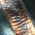
I was able to get a couple pics of the actual piece today. This is just mocked up for now.
-Jonathan
-Jonathan
- Attachments
-
- image.jpg (78.7 KiB) Viewed 2020 times
-
- image.jpg (68.13 KiB) Viewed 2020 times
Instagram- @superiorwelding/@learntotig
Twitter- @_JonathanLewis
https://www.learntotig.com
https://www.superiorweldandfab.com
https://www.youtube.com/+SuperiorWeldin ... ATHANLEWIS
Twitter- @_JonathanLewis
https://www.learntotig.com
https://www.superiorweldandfab.com
https://www.youtube.com/+SuperiorWeldin ... ATHANLEWIS
- weldin mike 27
-
Weldmonger
-
Posts:
-
Joined:Fri Apr 01, 2011 10:59 pm
-
Location:Australia; Victoria
jwright650
- jwright650
-
Ace
-
Posts:
-
Joined:Wed Dec 03, 2014 3:27 pm
I was hoping for a pic from the back side of the base plate.(the very bottom as it sits in the pics) 
IN the original post the top drawing appears to be missing some hidden lines, unless I'm not seeing the detail in the second drawing correctly. I envisioned the 4140 stub fitting through a hole in the base plate and welded on the bottom as well as the top.
IN the original post the top drawing appears to be missing some hidden lines, unless I'm not seeing the detail in the second drawing correctly. I envisioned the 4140 stub fitting through a hole in the base plate and welded on the bottom as well as the top.
John Wright
AWS Certified Welding Inspector
NDT Level II UT, VT, MT and PT
NACE CIP Level I Coating Inspector
AWS Certified Welding Inspector
NDT Level II UT, VT, MT and PT
NACE CIP Level I Coating Inspector
- Superiorwelding
-
Weldmonger
-
Posts:
-
Joined:Thu Jan 24, 2013 10:13 pm
-
Location:Eddy, TX
You are correct. The 4140 shaft sits through the 3" circle base, and will be welded from both sides. I can try to get you a pic but it is still sitting there like the pic shows so it might not be the best. The prints show better detail I just didn't post it. Technically I can't even post what I did.jwright650 wrote:I was hoping for a pic from the back side of the base plate.(the very bottom as it sits in the pics)
IN the original post the top drawing appears to be missing some hidden lines, unless I'm not seeing the detail in the second drawing correctly. I envisioned the 4140 stub fitting through a hole in the base plate and welded on the bottom as well as the top.
-Jonathan
Instagram- @superiorwelding/@learntotig
Twitter- @_JonathanLewis
https://www.learntotig.com
https://www.superiorweldandfab.com
https://www.youtube.com/+SuperiorWeldin ... ATHANLEWIS
Twitter- @_JonathanLewis
https://www.learntotig.com
https://www.superiorweldandfab.com
https://www.youtube.com/+SuperiorWeldin ... ATHANLEWIS
- Superiorwelding
-
Weldmonger
-
Posts:
-
Joined:Thu Jan 24, 2013 10:13 pm
-
Location:Eddy, TX
I can't get a pic of the actual bottom but here is a view from the print. Hope this helps.
-Jonathan
-Jonathan
- Attachments
-
- image.jpg (85.92 KiB) Viewed 2004 times
Instagram- @superiorwelding/@learntotig
Twitter- @_JonathanLewis
https://www.learntotig.com
https://www.superiorweldandfab.com
https://www.youtube.com/+SuperiorWeldin ... ATHANLEWIS
Twitter- @_JonathanLewis
https://www.learntotig.com
https://www.superiorweldandfab.com
https://www.youtube.com/+SuperiorWeldin ... ATHANLEWIS
jwright650
- jwright650
-
Ace
-
Posts:
-
Joined:Wed Dec 03, 2014 3:27 pm
That's what I wanted to see...thanksSuperiorwelding wrote:I can't get a pic of the actual bottom but here is a view from the print. Hope this helps.
-Jonathan
John Wright
AWS Certified Welding Inspector
NDT Level II UT, VT, MT and PT
NACE CIP Level I Coating Inspector
AWS Certified Welding Inspector
NDT Level II UT, VT, MT and PT
NACE CIP Level I Coating Inspector

4140 especially in heavy members is VERY sensitive and will easily crack (underbead) if weld bead placement/sequencing is not controlled.
I lost the procedures years ago... but this would give a good place to start if I were assigned to the task.
The configuration was a 2" thk. 36" dia. outer sleeve over a set of "J" slots in a 32"(?)O.D. X 2" thk inner sleeve.
Any ways, to join the two was a 45° double bevel on both ends which we preheated to 600°F (-0 + 75°max innerpass), welded with 12018C1 SMAW. The preheat was facilitated by heating the outer sleeve to to 600 while inner sleeve was left at ambient so thermal expansion would allow "marrying" of the two cylindrical parts. The screaming/screeching sound of the two parts (about 1 ton total weight) was blood curdling.
Post welding it was wrapped in asbestos (yes we used that stuff in the '70s...) and since I was not in charge of stress relief, I do not remember the post weld treatment specifications.
And similar to your device, this "Lifting device" was rated in excess of 1 million pounds capacity.
Additionally, I would recommend a 1-2 day delay for NDE (UT) prior to PWHT.
Last time I saw something with this tight of requirements for pre heat inter pass and cool down. They brought in a separate company to do all that. It took 2 guys a solid day to set up sensors and heaters. As it was worked on they would uncover just a section at a time and then basically say Go! Welding in a planed pattern all the while they would start and stop the welding per the heat treat guys. It required a very specific engineered plan and procedure.
I have more questions than answers
Josh
Josh
- Otto Nobedder
-
Weldmonger
-
Posts:
-
Joined:Thu Jan 06, 2011 11:40 pm
-
Location:Near New Orleans
Though we're digging up an old topic on a problem already solved, I have to say I like the interest, and the different takes on performing the task.
Welding is absolute proof of the old saw, "There's more than one way to skin a cat." Makes me want a pair of TIG gloves made from catskin...
Steve S
Welding is absolute proof of the old saw, "There's more than one way to skin a cat." Makes me want a pair of TIG gloves made from catskin...
Steve S
Return to “Mig and Flux Core - gas metal arc welding & flux cored arc welding”
Jump to
- Introductions & How to Use the Forum
- ↳ Welcome!
- ↳ Member Introductions
- ↳ How to Use the Forum
- ↳ Moderator Applications
- Welding Discussion
- ↳ Metal Cutting
- ↳ Tig Welding - Tig Welding Aluminum - Tig Welding Techniques - Aluminum Tig Welding
- ↳ Mig and Flux Core - gas metal arc welding & flux cored arc welding
- ↳ Stick Welding/Arc Welding - Shielded Metal Arc Welding
- ↳ Welding Forum General Shop Talk
- ↳ Welding Certification - Stick/Arc Welding, Tig Welding, Mig Welding Certification tests - Welding Tests of all kinds
- ↳ Welding Projects - Welding project Ideas - Welding project plans
- ↳ Product Reviews
- ↳ Fuel Gas Heating
- Welding Tips & Tricks
- ↳ Video Discussion
- ↳ Wish List
- Announcements & Feedback
- ↳ Forum News
- ↳ Suggestions, Feedback and Support
- Welding Marketplace
- ↳ Welding Jobs - Industrial Welding Jobs - Pipe Welding Jobs - Tig Welding Jobs
- ↳ Classifieds - Buy, Sell, Trade Used Welding Equipment
- Welding Resources
- ↳ Tradeshows, Seminars and Events
- ↳ The Welding Library
- ↳ Education Opportunities