What welding projects are you working on? Are you proud of something you built?
How about posting some pics so other welders can get some ideas?
av8or1

As I have mentioned in another thread a short while ago, I have been doing automotive related projects for the past few months. Thus no real fabrication to speak of, at least in regard to an actual fab project of one sort or another. I've missed the forum and the folk here (hey Oscar!) but this current project is a build for the wife-eee, so that has precedent over most anything else. Recently I came across a sub-project in this build that will be fabrication related. For that reason, I decided to create a thread regarding the fab stuff ... mostly just because I wanted an excuse to visit the forum and catch-up with the goings-on. :D

Quick background (apologies if this is a repeat - I can't recall discussing this previously): the wife-eee drives a 2006 Ford Crown Victoria. It is her daily. We call it "Whitey" because ... well it's white. It's a solid beast in general so we're happy with it. Or so I thought. That was until the day I brought home another 2006 Crown Victoria. It was supposed to be a parts car for Whitey. However this "parts car" is painted in Dark Blue Pearl. That was a factory color and this was a factory paint job. The wife-eee sees the color and proclaims "I want this!" Ooooohhhhhhh....I groaned (on the inside, naturally). I've been rebuilding this ... ahem ... thing ever since. Fellas, this was a parts car if there ever was one. Damage to the body that was masked over; a most malodorous interior that reeked of cologne so badly you could hardly stand to sit in the thing; misaligned body panels; a transmission that launched into reverse ('cause the third gear planetary and low reverse drum were welded together when the previous owners ran it low on fluid; wiring that was spliced together without solder, without electrical tape and just thrown in to the loom; ... well you get the idea. The more I dug, the more issues I found. It was so bad that I became fed up one weekend and used the gantry to yank the friggin body off of the frame:
frame off 2.jpg
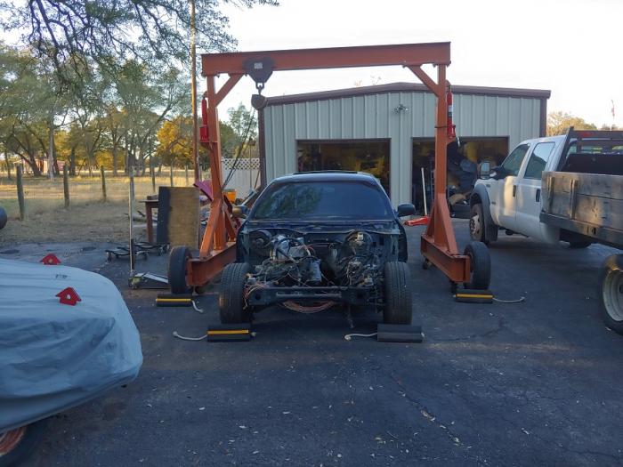
frame off 2.jpg (61.22 KiB) Viewed 11897 times
frame off 10.jpg
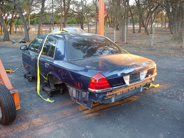
frame off 10.jpg (231.85 KiB) Viewed 11897 times
I documented (post-mortem) the gantry build too, FWIW. https://forum.weldingtipsandtricks.com/ ... =9&t=15597

Having a gantry around sure comes in handy at times, especially when you don't have a forklift. I digress.

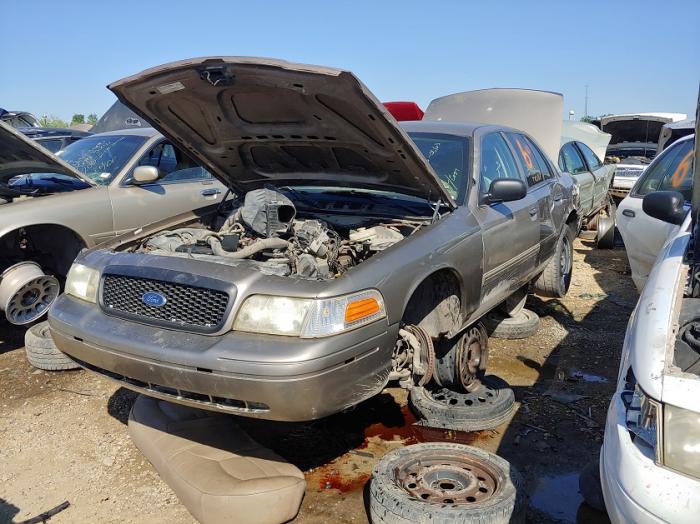
Now to bring the discussion 'round full circle to the little fabrication project that I mentioned at the outset of this post. While working on this project I routinely visit automotive salvage yards. I do so for the purpose of finding parts that are no longer being manufactured. For other reasons too. A good example are the front and rear brake calipers and carriers. Sure, you can purchase these new but those are aftermarket offerings. I prefer to run OEM whenever possible. You can't buy new Ford OEM calipers/carriers. And so a salvage yard is my only option. Sooooo ... I was at a yard a couple of weeks ago on the hunt for various components. I came across this 2006 CVPI (which is an acronym for Crown Victoria Police Interceptor):
oil cooler 1.jpg
oil cooler 1.jpg (72.34 KiB) Viewed 11897 times
When I noticed a skid plate underneath the engine. You might think that those are common. However on all of the CVPIs that I have seen during the past two years that I have been building this vehicle, this is the first skid plate that I have encountered. I also noticed that all of the components that resided above this skid plate were in quite-good condition. The oil cooler, rad hoses, fan, belt, pulleys, forward portion of the pan, just everything. That made sense to me, after all this critter was protecting the internals rather well. And of course I've seen this type of thing in the past, though on other vehicles. Anyway for multiple reasons, I snatched the skid plate and brought it home:
skid plate 1.jpg
skid plate 1.jpg (85.39 KiB) Viewed 11897 times
It was shaped perfectly to live where it did, just as though it came from Ford that way. It didn't of course, just sayin'. However as can been seen above it definitely saw some action in its life and could use a bit of freshening up. It's a relatively heavy duty critter I might add, well, for what it is anyway. I haven't measured it but by feel it is either 10 or 11 gauge steel, perhaps slightly thicker than that even. Yeah ok I'll measure it the next time I'm in the workshop. :D

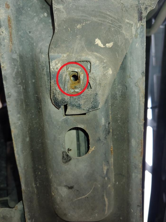
Anyway that isn't the fab part of the project. That comes in the form of the mounting. You see, whatever police department fabricated and installed this critter did an arguably crude job of installing it. At least WRT the rear mounting they did. Standard fare for a cruiser, I understand that, but still... they simply drilled a hole through the pax side foot of the K-member:
skid plate 2.jpg
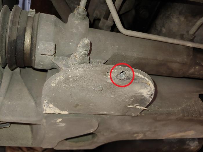
skid plate 2.jpg (40.41 KiB) Viewed 11897 times
Then ran a nut-n-bolt-n-washer through it, tightened it down and called it a day. There was no means of securing the plate on the driver's side whatsoever. At least in the front there were two mounting points; they came by way of the radiator support, which already has two bolts with captives on it:
skid plate 3.jpg
skid plate 3.jpg (76.93 KiB) Viewed 11897 times
That much is to-the-good. However the aft thing ... yeah I won't replicate that mounting. And so that is where the fab lies: develop some means of mounting the skid plate to the K-member that is non-obtrusive yet solid and functional. Originally I had thought that I would utilize some of the thread on the mounting studs (the pax side stud can be seen in the picture where the hole in the K-member is shown). However my preference is drifting towards the notion of some type of clamp that rides over the K-member in the center, thus giving the plate only three mounting locations. The idea being that in order to change the oil, you would need only to remove the front two bolts and loosen the rear, then rotate the plate to the pax side so that you could access the pan bolt. This would avoid the need to drop the plate altogether just to change the oil. That said, I am open to ideas if you have any to throw out there. That is part of the reason I am posting this ... to see if there is any feedback.

Note that I decided to close the holes that were drilled for the purpose of the previous aft installation approach:
skid plate 4.jpg
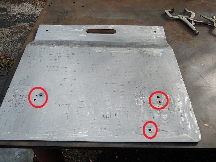
skid plate 4.jpg (49.55 KiB) Viewed 11897 times
All you need for something like that is a rudimentary box, so I grabbed the mini-me:
skid plate 5.jpg
skid plate 5.jpg (80.2 KiB) Viewed 11897 times
Welded the holes and had it in self-etch in just a few minutes:
skid plate 6.jpg
skid plate 6.jpg (66.6 KiB) Viewed 11897 times
And so: this is what has been occupying my free time (what little time I have that is!) as of late. I haven't forgotten about the smoker build (different thread). I simply haven't revisited that project.

Anyway take care, thanks! I hope everyone had a good holiday weekend!
User avatar
  • Posts:
  • Joined:
    Thu Dec 26, 2013 12:41 am
  • Location:
    Laredo, Tx

Welcome back! good to see you're keeping busy :)
Image
av8or1

Oscar wrote:Welcome back! good to see you're keeping busy :)
Thank you sir! I hope that all is well with you in South TEXAS. Still gotta do a TEXAS meetup someday...

Since my last post I've continued working on the build for the wife-eee. However that work is automotive in nature so I haven't mentioned it here. I circled the wagons back 'round to the skid plate tonight though, and so I have an update. I circled those wagons primarily because I need to finish the fab on the skid plate. It's consuming needed space in the workshop and I almost tripped on it. Twice. With that in mind I mounted the rebuilt steering rack:
steering 115.jpg
steering 115.jpg (62.14 KiB) Viewed 11714 times
And then the skid plate:
steering 118.jpg
steering 118.jpg (43.82 KiB) Viewed 11705 times
Which is held in position on the front end by two removable captives:
steering 119.jpg
steering 119.jpg (59.16 KiB) Viewed 11714 times
And so the task is to fabricate some means of securing it on the aft end of the plate, which just-so-happens to be located near the front crossmember. The plan is to utilize the steering rack studs as a means of obtaining the most rigid mounting. Using those isn't a problem in the abstract, so long as you don't run afoul with the steering geometry. And the way to avoid that is to firmly mount the rack against the crossmember, then place your bracketry forward of the rack, in-between the rack and the stud nuts. Ok so far, so good. Note however that there is more thread available on the pax side:
steering 116.jpg
steering 116.jpg (44.76 KiB) Viewed 11714 times
There is a boss on the rack housing that will limit the thickness of the bracket that can be built. However it won't factor into the equation much because my planned thickness was less than that limit already. Then there is the driver's side:
steering 117.jpg
steering 117.jpg (50.17 KiB) Viewed 11714 times
Issues abound. Less thread area to play with and significant interference from another boss on the rack, the bottom of the pinion housing and the pinion dust cover. For that reason, the bracket that I will fab will likely need to be of the 90-degree design (L-shape). The idea being that you simply remove the nut, slide this bracket over the stud, and then re-tighten the nut. The bracket has a hole in it just larger than the diameter of the stud. It extends both forward and laterally to the side toward the wheel (respectively). That bracket is then welded to the top of the skid plate. With this design, installation would involve the mounting of the plate onto the studs, securing the skid plate's brackets to the studs with the nuts, and then securing the front of the plate to the radiator support via the captives. Removal would be the opposite of installation.

Feedback welcomed. That's all I have for the time being. Hope all is well!
User avatar
  • Posts:
  • Joined:
    Thu Dec 26, 2013 12:41 am
  • Location:
    Laredo, Tx

I thought that "stud" was really a through-bolt on Ford's, at least on mine I seem to recall it is. I'll have to check my car.
Image
av8or1

Well, in the case of a Ford Panther (Crown Victoria, Grand Marquis, Towncar, Marauder) the steering rack stud is merely a solid metal rod that has threads on both ends. One end is threaded into the front crossmember. The rack slides onto the stud, covering the non-threaded portion of the stud. Then the nut that secures the rack to the crossmember is threaded on the other end. I'll take a picture today and post it later.

Thanks!

And here is that picture:
steering 120.jpg
steering 120.jpg (69.83 KiB) Viewed 11683 times
There is a hex head visible on the right side of the bolt in this picture. That is 8mm in size and must be the end that faces outward from the crossmember, since it is this hex head that you throw a socket onto in order to install or remove the stud. 'Course there is the possibility that the stud won't wanna leave its home in the crossmember due to rust, etc. and so you can strip this hex head if you use a 1/2" impact to attempt to remove the stud. Ask me how I know. :lol:
Last edited by av8or1 on Sat Jun 19, 2021 6:34 pm, edited 2 times in total.
User avatar
  • Posts:
  • Joined:
    Thu Dec 26, 2013 12:41 am
  • Location:
    Laredo, Tx

lol. Oh ok, gotcha.
Image
av8or1

With the holiday today we had family stuff going on all weekend. I had time enough to begin the fabrication of the brackets 'n that was it. The driver's side:
skid plate 7.jpg
skid plate 7.jpg (33.38 KiB) Viewed 11626 times
And pax:
skid plate 8.jpg
skid plate 8.jpg (38.72 KiB) Viewed 11626 times
Neither of which would remain in the 90-degree position long enough for me to snap a picture dontchaknow. Anyway I laid them out:
skid plate 9.jpg
skid plate 9.jpg (48.1 KiB) Viewed 11626 times
Drew the customary outlines and will apply the cookie cutter tomorrow (hopefully):
skid plate 10.jpg
skid plate 10.jpg (53.99 KiB) Viewed 11626 times
In regard to the aft mounting design/approach, I did consider the bolt-through-a-plate idea. That would enable you to leave the bracket in place on the steering rack stud whenever you wanted to remove the skid plate. Just not sure that I want the hassle of two more bolts and I would prefer the cleaner asthetic of no aft bolts from a design perspective. However it would be a pain to be required to remove the two steering rack stud nuts anytime that you needed or wanted to remove the skid plate. It is important to note that this skid plate does not extend far enough aft so as to cause an issue in regard to an oil change. However I am considering fabricating anotherplate to cover the goodies that reside aft of the crossmember. TBD. As for the aft bolt issue though, well I dunno ... still debating. :lol:

Happy Father's Day!
av8or1

Crazy busy week. No time for much of anything project-wise. Tonight I managed to apply the cookie cutter to the plate templates for the skid plate brackets. Then grind, drill and bend them into rough shape:
skid plate 11.jpg
skid plate 11.jpg (34.72 KiB) Viewed 11571 times
skid plate 12.jpg
skid plate 12.jpg (39.43 KiB) Viewed 11571 times
They came out ok-ish. I've decided to go with the bolts-n-plates approach, as opposed to merely welding them to the skid plate. The primary reason being the simplicity of removal if/when needed. With that decision in-hand I drilled the holes larger than necessary to provide a little wriggle room after I weld on the supports to the brackets, then drill the holes through both the skid plate and the brackets for the bolts. I'll utilize two per side and use captive nuts welded onto the top of the bracket supports (ergo "feet"). Fiddly, a bit time-consuming, but I prefer to pay that price now rather than later.

Hope all is well!
av8or1

Well fellas ... bunk. I snatched time today to play around with the skid plate for Ol' Blue just a bit. I cut the new brackets (the "feet"), grinded them and refined their shape such that they would clear the front crossmember's feet by a good margin:
skid plate 13.jpg
skid plate 13.jpg (239.7 KiB) Viewed 11462 times
I then performed multiple, repeated test fittings of the brackets in relation to the steering rack and the skid plate. Once the alignment thereof was satisfactory, I welded the "feet" to the previously-fabricated brackets that mount to the steering rack. Cleaned the resulting bracket "pair" and applied self-etch. Drilled a couple of holes into the feet. Mounted the brackets and marked the holes on the skid plate. Removed the brackets and skid plate from the frame. Drilled the holes in the skid plate that would correspond to those in the feet. Then tested those new countersink bits (which were ok, no better than any others I've used) on the bottom side of the skid plate. Installed the hardware and gave it a test fit. Everything aligned well. Thumbs up. The following is the product of that work:
skid plate 14.jpg
skid plate 14.jpg (32.01 KiB) Viewed 11462 times
In the event that you are wondering what the dark areas on the feet are, that is where I ground off whatever happened to be there, including welding splatter, primer, whatever. I had the skid plate out and on the workbench in preparation for welding the captive nuts onto the feet. With that done, the fabrication would be essentially complete. Hmmmmm...not so fast.

Yeah I dunno ... all of the above work for what in the end may not be used. Fellas, I'm tellin' ya, by having the brackets installed onto the skid plate, you give yourself an advantage. At least in a way you do. See, during the multiple test fits after I had finished whatever work I was doing at the time, I noticed that the installation of the skid plate was *so* much easier when I left the brackets bolted to the skid plate. This was because I could slide the plate onto the steering rack studs and then release it entirely. I would then be hands-free while the skid plate just hang out there. I then fiddled with securing the front bolts, which were nicely aligned by the mere action of sliding the skid plate with its brackets all the way against the steering rack. Removal of the plate was easier too because I could just unthread those front bolts and not worry about the skid plate dropping onto me or any part thereof since it was supported by the studs. It would then slide forward and off of the studs whenever I wanted and do so with ease. By this point though I had two free hands on it and thus it was a doddle to manage. I can just imagine trying to support this thing while fiddling with what would be the first of 4 small bolts. Easier with a floor jack, sure, but still a pain to align the thing to get that first bolt installed. When I left the brackets mounted to the skid plate, it was simple to put into position with only two hands (as described above), no floor jack or other support aid necessary. The downside to the brackets being permanently welded to the plate would obviously be the required removal of the steering rack stud nuts if you wanted or needed to remove the plate. However those are easily enough had, so ... yeah ... overall it was just much easier to install and remove with the brackets left on the plate than with them off.

And with that I stopped work for the night in order to give this one a re-think. After a sleep-think I have yet to decide whether to return to Plan A...

Hope you had a good 4th!
av8or1

Wow. Been a while since I've been on the forum. Thought I'd provide an update on this mini-me type of build. I ended up foregoing the 4 bolts and just welding the brackets and their plates to the main body of the skid plate. You can kinda see the stitch welds in this final installation test picture:
skid plate final.jpg
skid plate final.jpg (225.99 KiB) Viewed 9621 times
Ultimately the fiddly-ness associated with the 4 small bolts was more hassle than I wanted to contend with whenever time came to do anything with the skid plate. And welding them in certainly makes both installation and removal easier since the plate will just hang on the steering rack bolts while you cinch up the forward bolts into those captives.

Anyway that is where it ended up, FWIW.

Thanks!
Post Reply