Some meticulous work going on here - well done.
Watching this build with interest.
Kym
What welding projects are you working on? Are you proud of something you built?
How about posting some pics so other welders can get some ideas?
How about posting some pics so other welders can get some ideas?

- MosquitoMoto
-
Weldmonger

-
Posts:
-
Joined:Sat Aug 01, 2015 8:38 am
-
Location:The Land Down Under
LS Customs
- LS Customs
-
Ace

-
Posts:
-
Joined:Tue Feb 23, 2016 11:56 pm
thanks... working on a welding positioner also... almost done with both... cant wait to try it all out...MosquitoMoto wrote:Some meticulous work going on here - well done.
Watching this build with interest.
Kym
- MosquitoMoto
-
Weldmonger
-
Posts:
-
Joined:Sat Aug 01, 2015 8:38 am
-
Location:The Land Down Under
Excellent...keep those photos coming!LS Customs wrote:thanks... working on a welding positioner also... almost done with both... cant wait to try it all out...MosquitoMoto wrote:Some meticulous work going on here - well done.
Watching this build with interest.
Kym
Kym
LS Customs
- LS Customs
-
Ace
-
Posts:
-
Joined:Tue Feb 23, 2016 11:56 pm
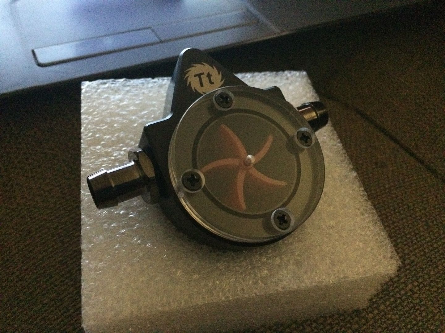
flow indicator sight came in.. waiting on a rivet nut gun and going to use some nutserts to attached the panels onto the enclosure... the ones needing to come off and on to access components... tool will be here monday... hopefully be testing this out by tuesday...
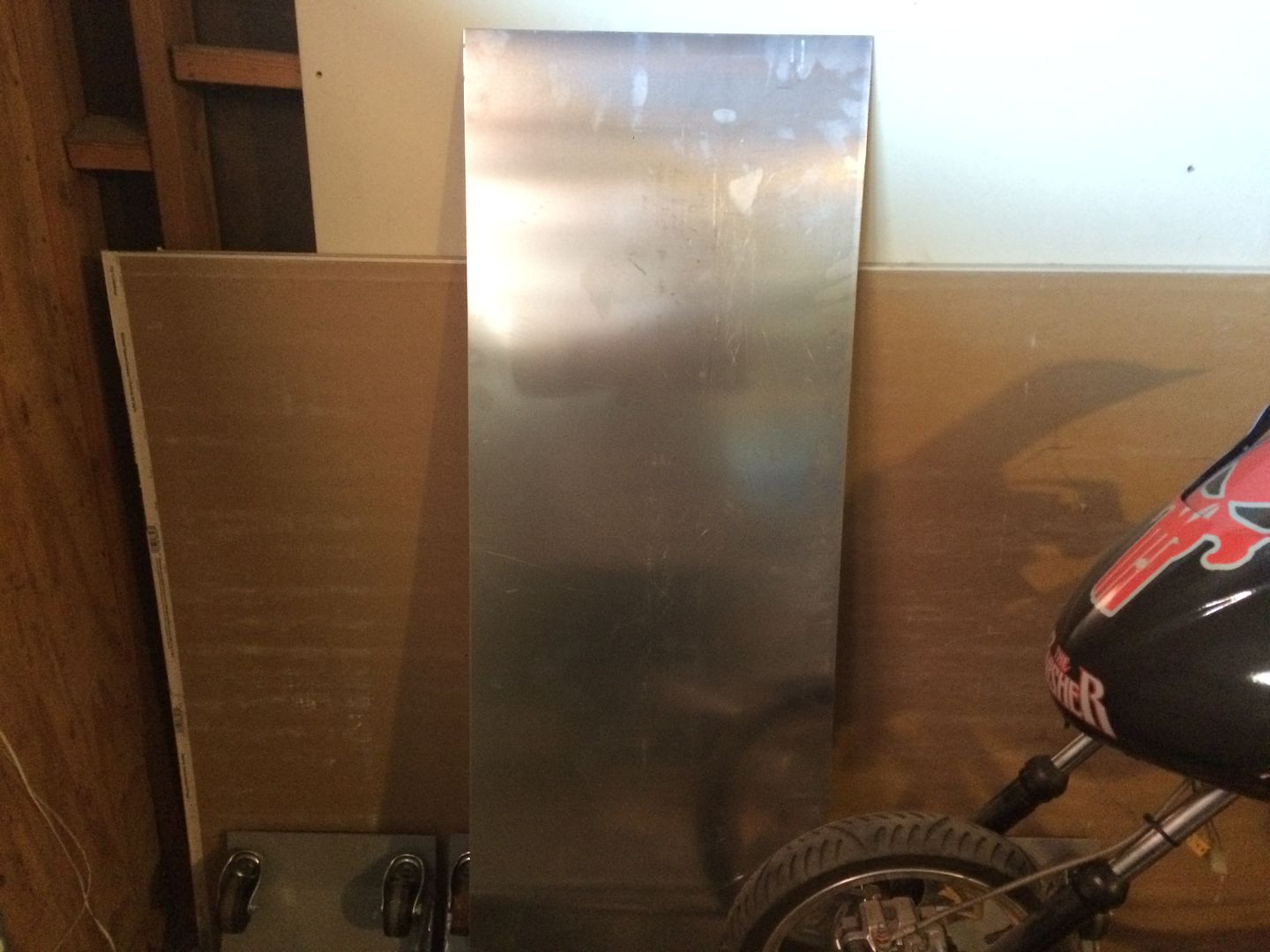
picked up some 063 and cut it down to fit... going to mount the quick connects, flow sight, and an iec module for switched power on the panels... i will use some square tubing i have laying around to start on a cart, to hold the tig welder and the cooler... to try to make it as clean a setup as i can, with what i have...
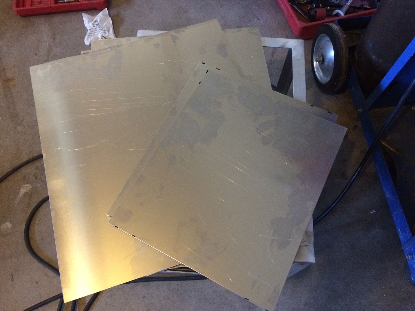
bought a half sheet so, i have a bit left over to practice welding with also...
picked up some 063 and cut it down to fit... going to mount the quick connects, flow sight, and an iec module for switched power on the panels... i will use some square tubing i have laying around to start on a cart, to hold the tig welder and the cooler... to try to make it as clean a setup as i can, with what i have...
bought a half sheet so, i have a bit left over to practice welding with also...
LS Customs
- LS Customs
-
Ace
-
Posts:
-
Joined:Tue Feb 23, 2016 11:56 pm
as I left the welds untouched on the sides of this enclosure... i marked the panel and trimmed out around where the welds would be on each side... if not the panels wouldnt sit flat...
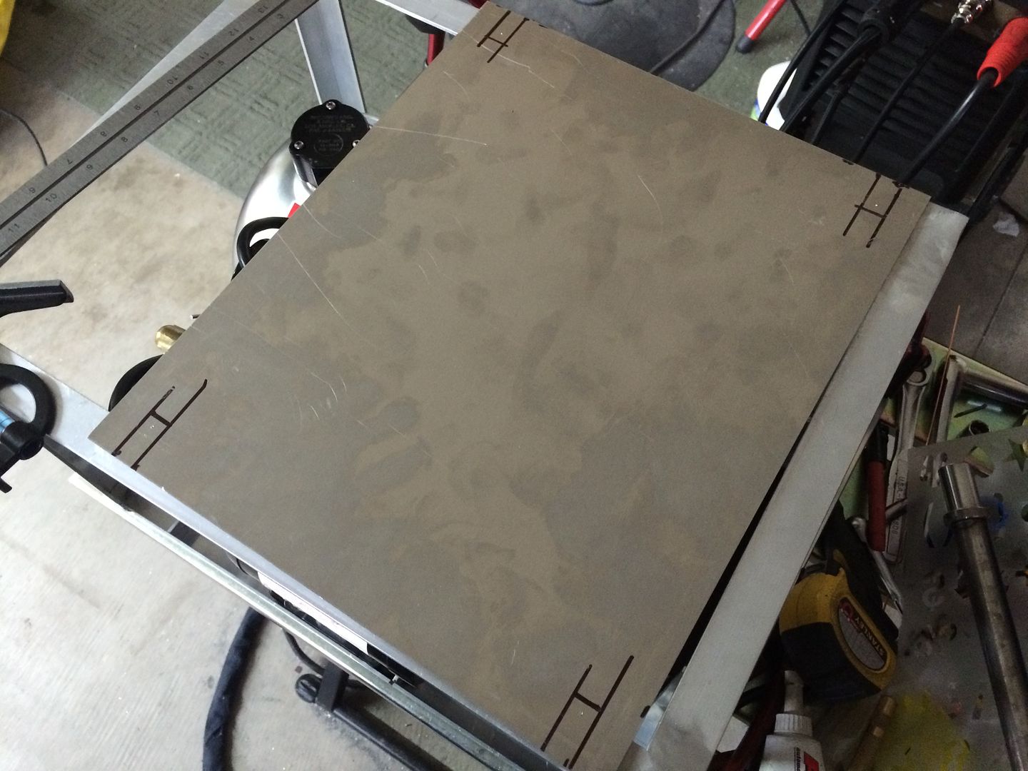
Last edited by LS Customs on Mon Aug 22, 2016 2:16 am, edited 2 times in total.
LS Customs
- LS Customs
-
Ace
-
Posts:
-
Joined:Tue Feb 23, 2016 11:56 pm
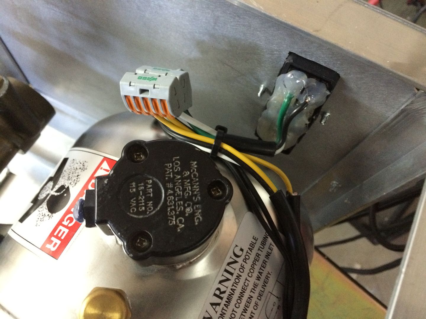
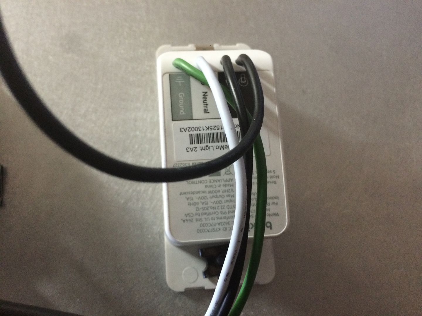
i decided to use an iec module (i have a couple laying around, and these are very inexpensive) to power the components needing power...
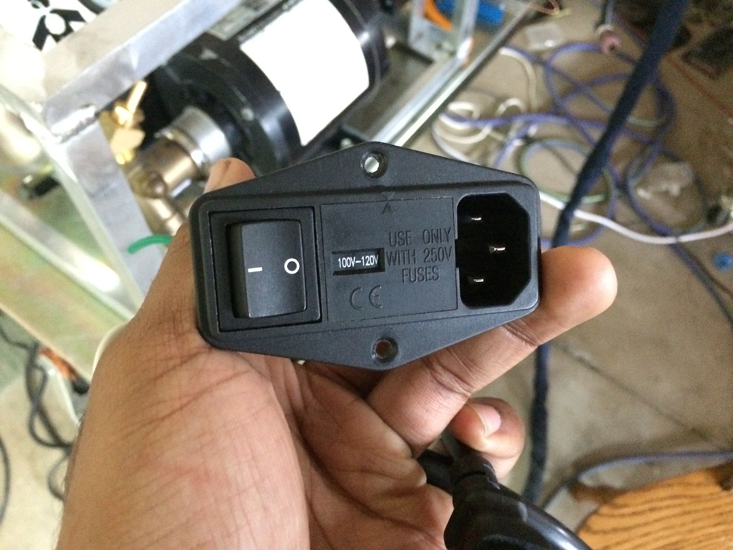
I soldered the wires to the back of this module.. I did this failry quick and ended up soldering the green where the white should be (THE WHITE IS GROUND)... but i know this, so when i wired the fan and pump motor, they were wired properly.. im mentioning this in case someone reads it or looks at the pic and wires this up this way.. hopefully the read this.. but later on in this thread, i will try to remember to highlight this again...
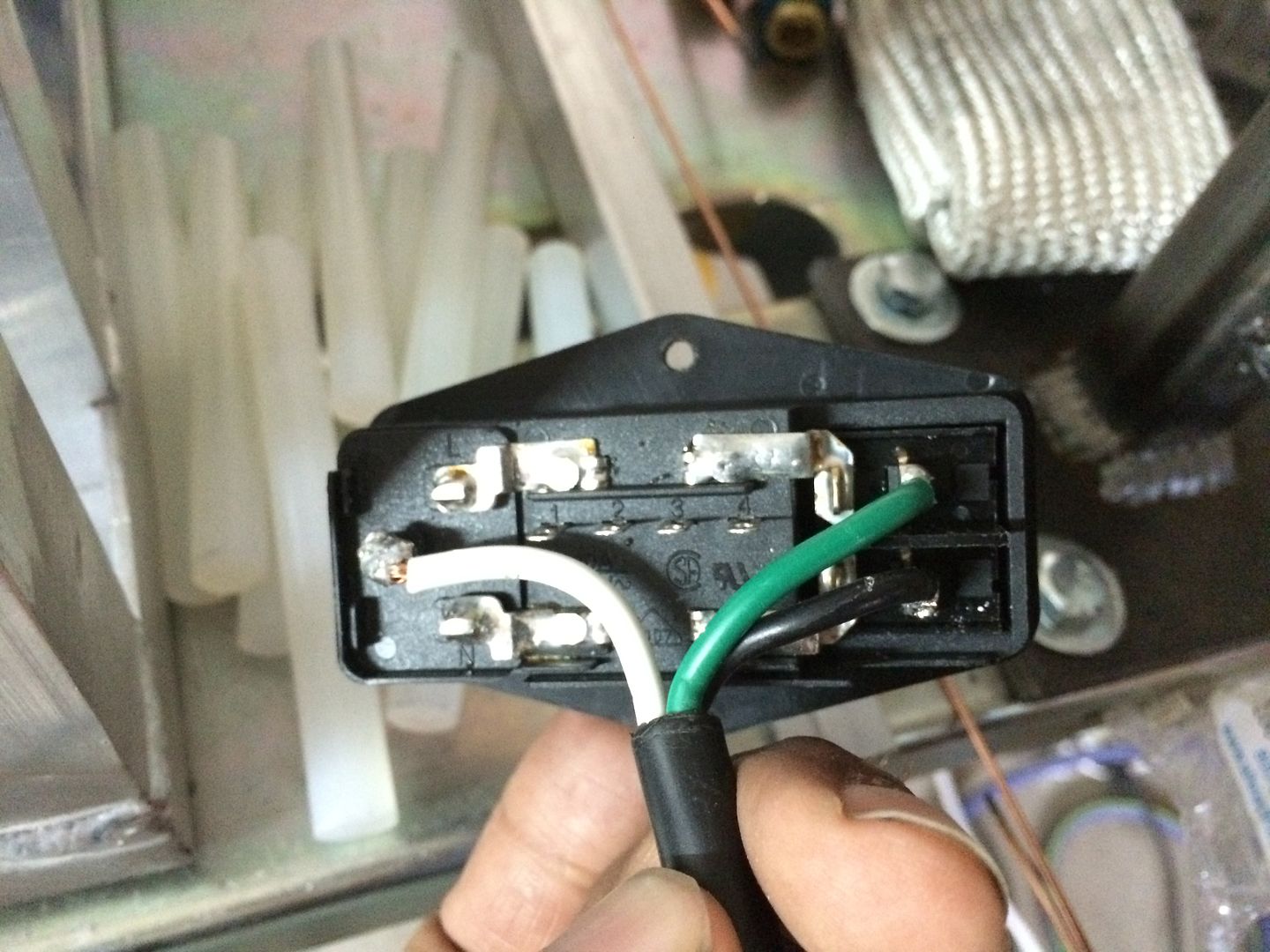
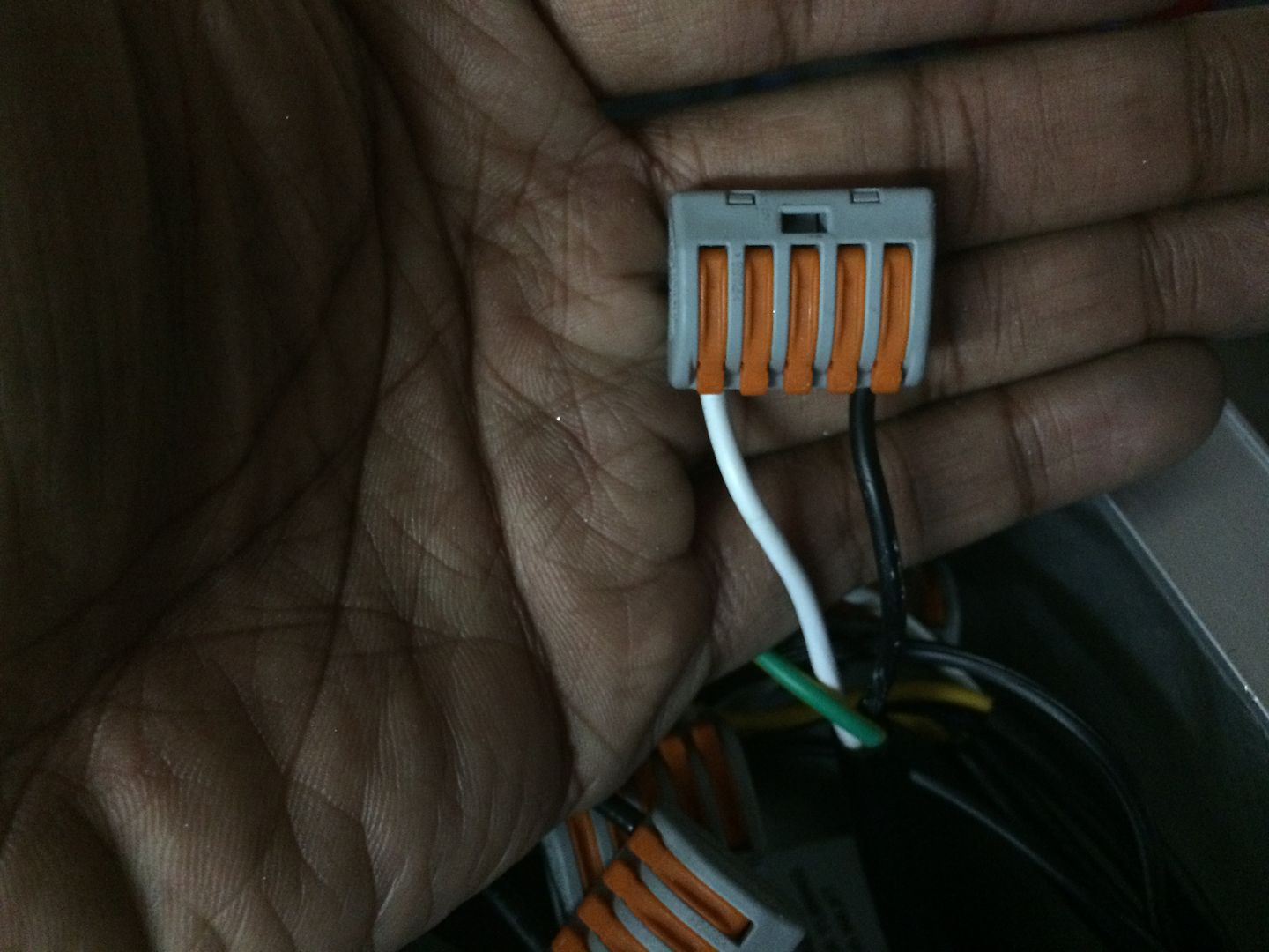
i also have these nicer connectors laying around.. i like them better than wing nuts... I may be adding additional components, like another fan to the back of the enclosure, pulling air from the inside out... as the fan on the radiator is pulling air from the outside in... cooling the radiator and the back of the motor for the pump... but I dont think an additional fan is necessary... i will add it if it seems like there is a lot of heat being retained inside the enclosure..
I soldered the wires to the back of this module.. I did this failry quick and ended up soldering the green where the white should be (THE WHITE IS GROUND)... but i know this, so when i wired the fan and pump motor, they were wired properly.. im mentioning this in case someone reads it or looks at the pic and wires this up this way.. hopefully the read this.. but later on in this thread, i will try to remember to highlight this again...
i also have these nicer connectors laying around.. i like them better than wing nuts... I may be adding additional components, like another fan to the back of the enclosure, pulling air from the inside out... as the fan on the radiator is pulling air from the outside in... cooling the radiator and the back of the motor for the pump... but I dont think an additional fan is necessary... i will add it if it seems like there is a lot of heat being retained inside the enclosure..
Last edited by LS Customs on Mon Aug 22, 2016 2:17 am, edited 1 time in total.
LS Customs
- LS Customs
-
Ace
-
Posts:
-
Joined:Tue Feb 23, 2016 11:56 pm
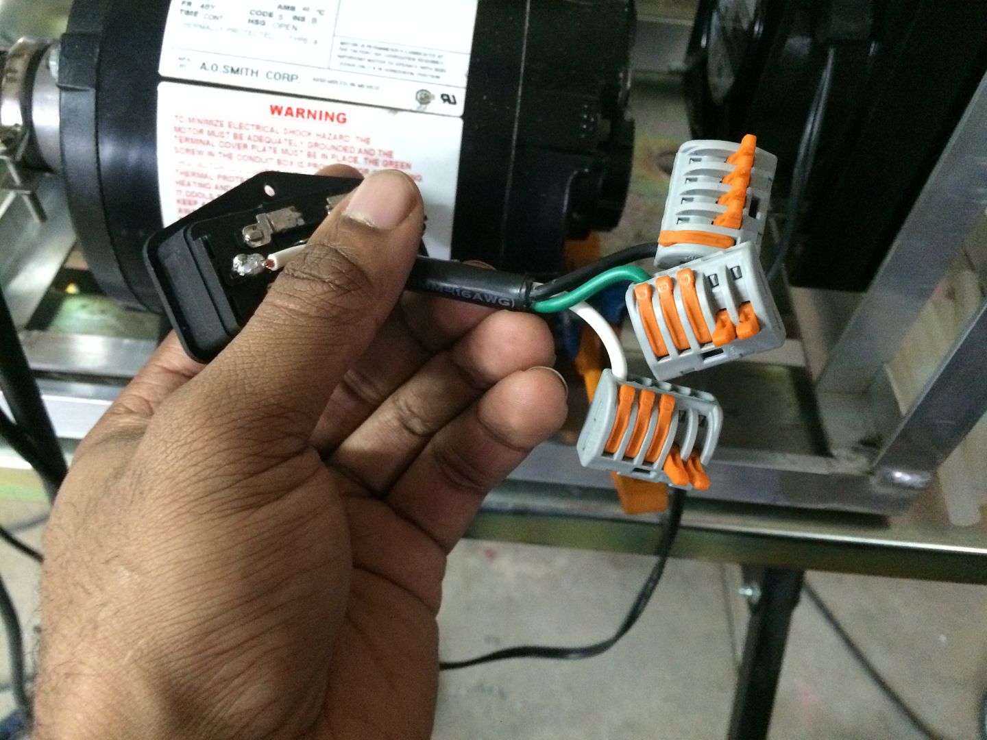
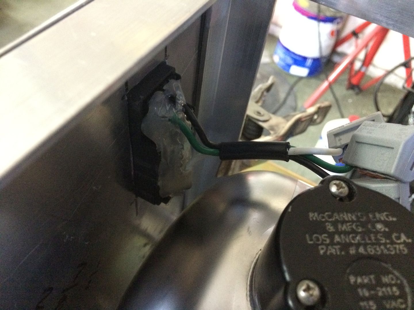
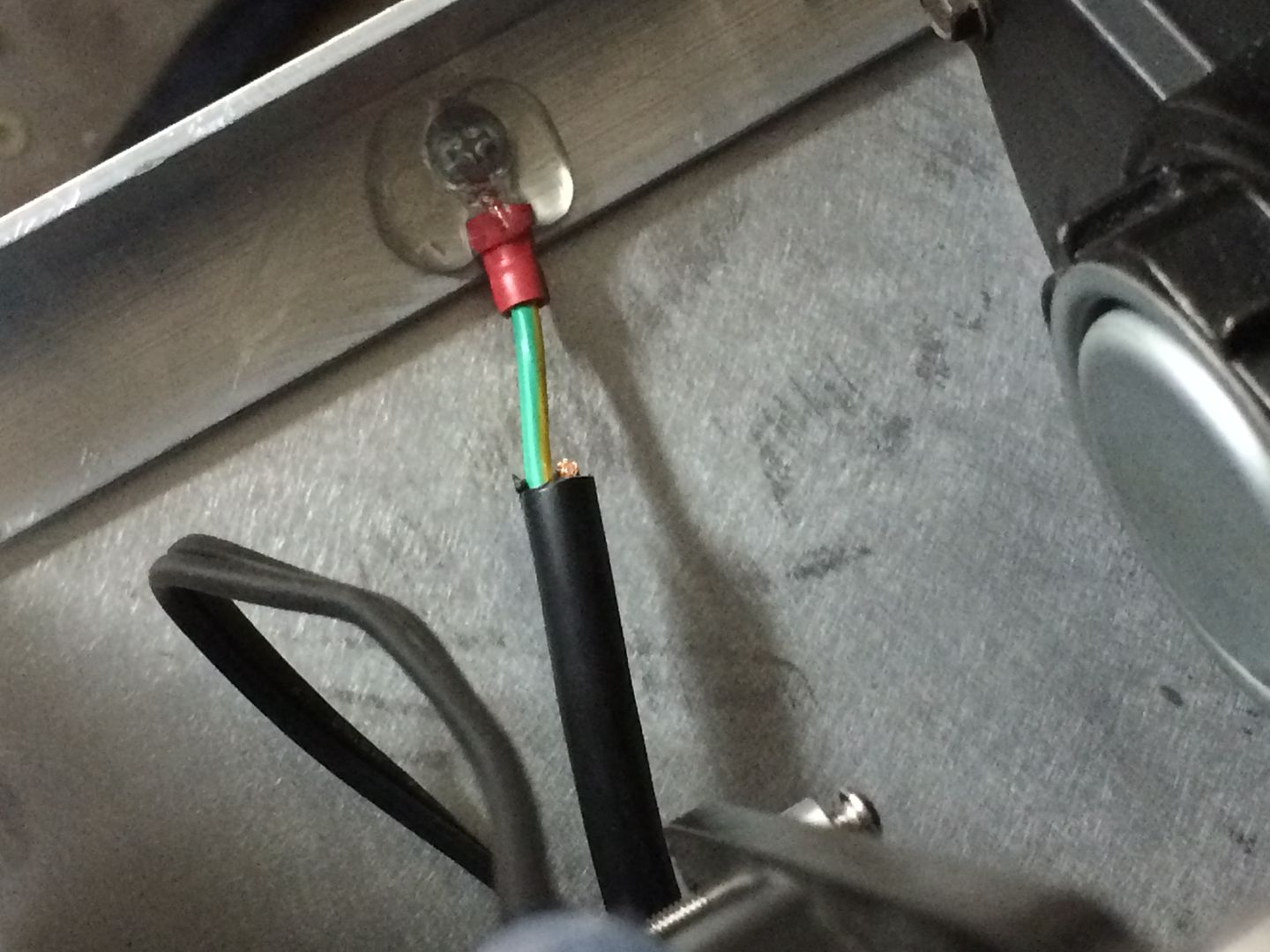
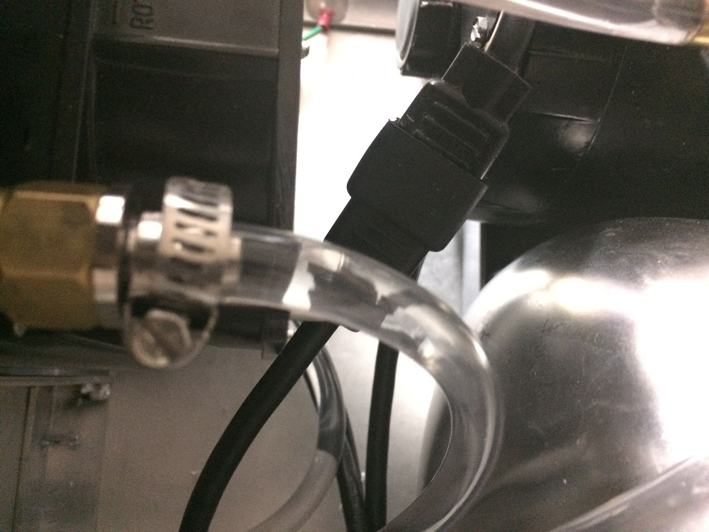
whenever i do any wiring, where the components will be outside, (in a vehicle, etc), or where moisture may be present, I routinely protect the area using a hot glue gun and i typically use glue, that is designed to hold up to a little more heat... this protects the wiring, while also allowing for me to be able to very easily peel the coating off, if i need to access the terminals at a later time...
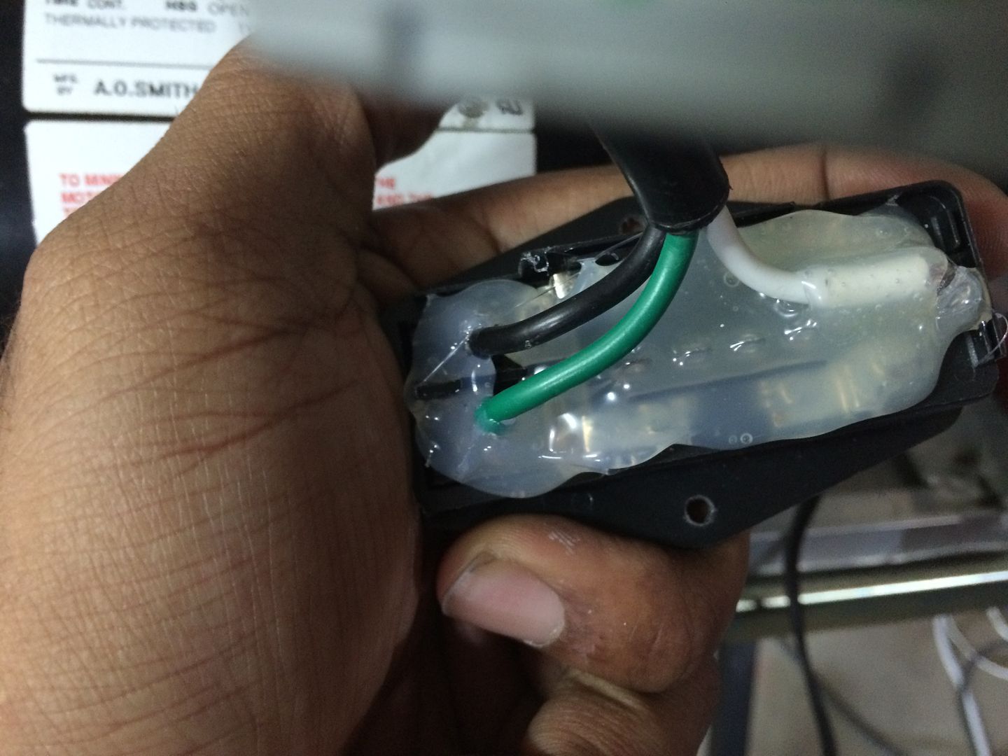
also did this on the fans wiring terminal.. and this is as far as the plug pushes on.. as you can see the two terminals are a little exposed.. using the hot glue gun, helps to protect them, while also, helping to keep the plug secure...
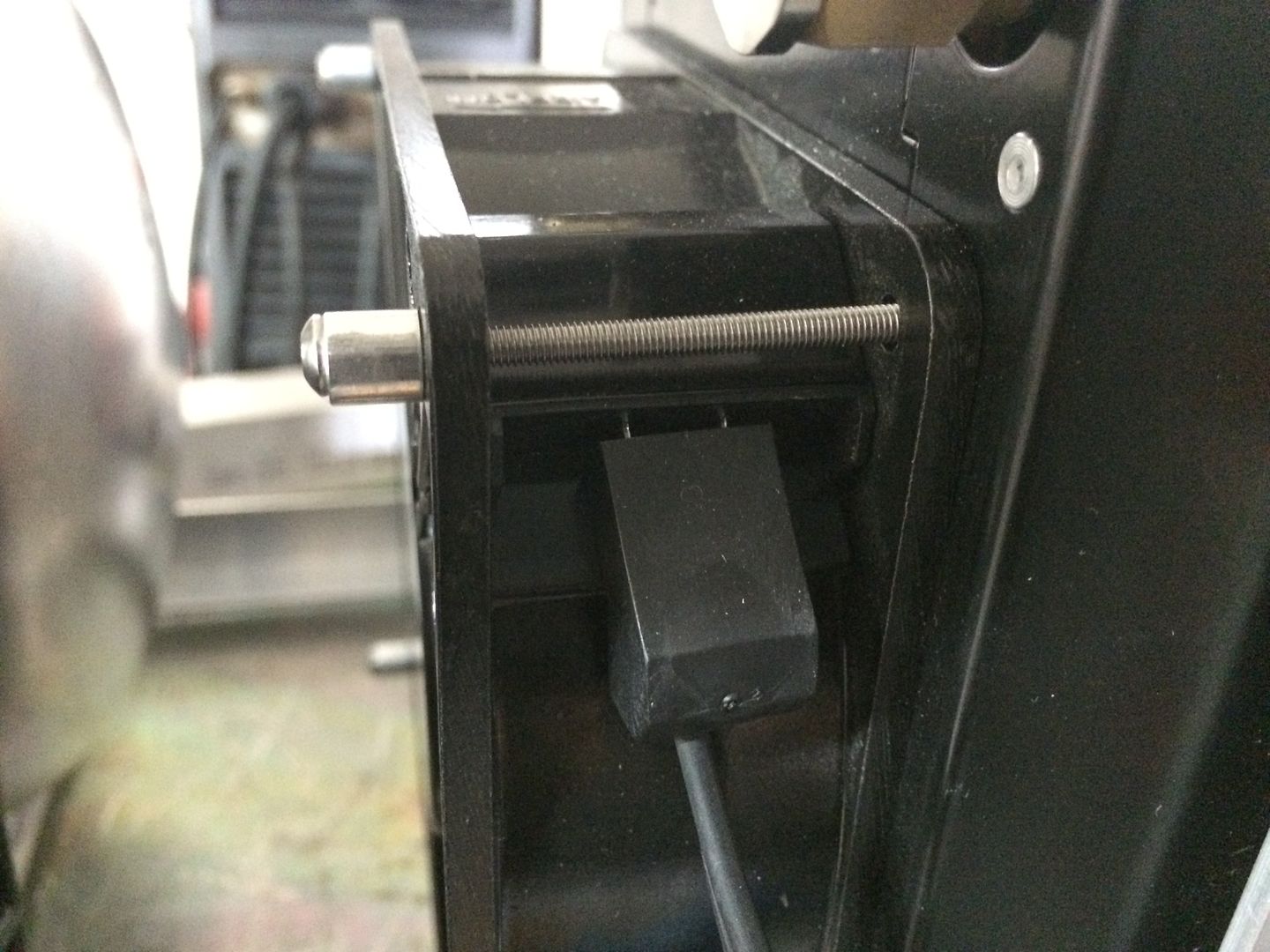
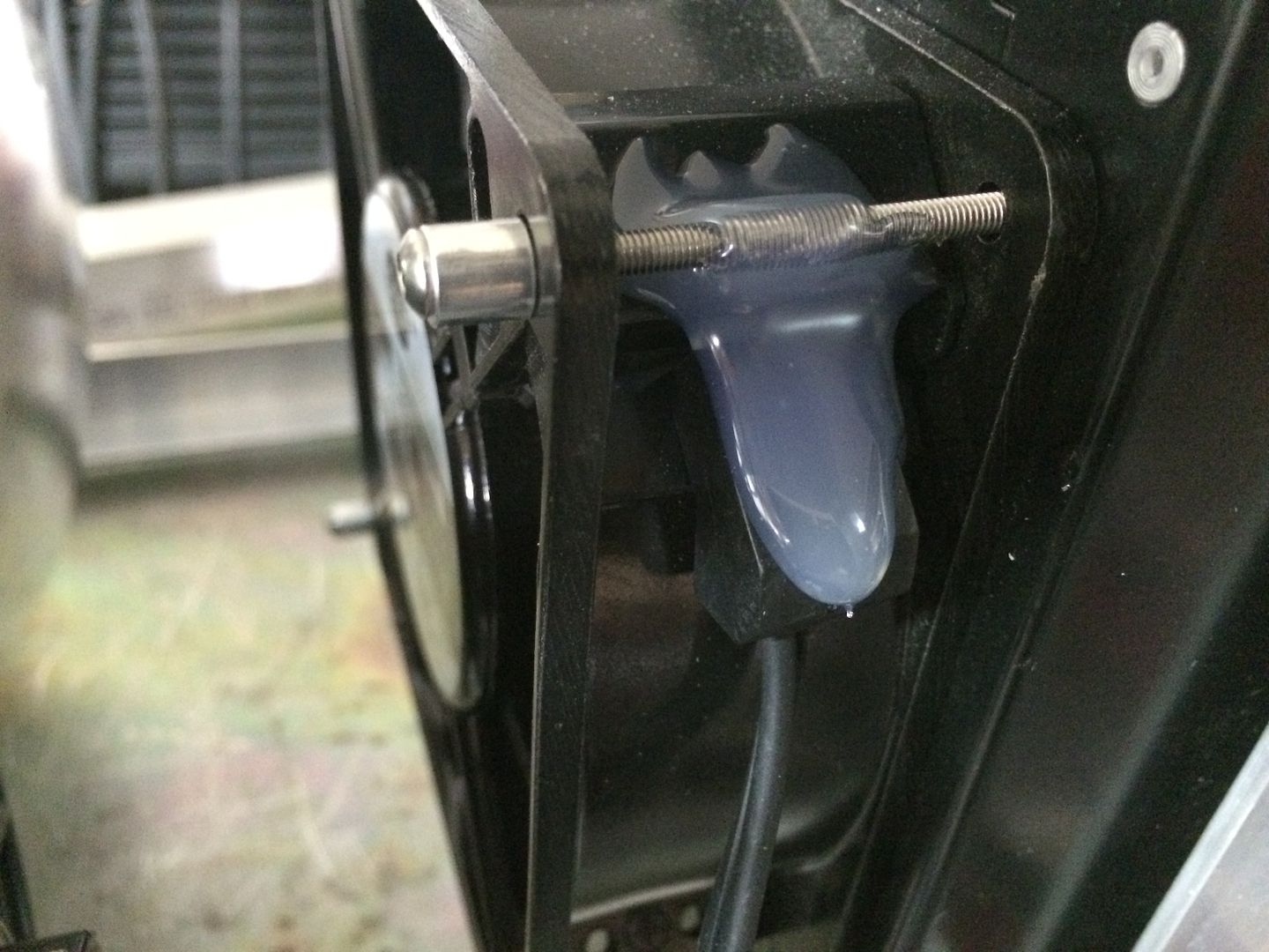
also did this on the fans wiring terminal.. and this is as far as the plug pushes on.. as you can see the two terminals are a little exposed.. using the hot glue gun, helps to protect them, while also, helping to keep the plug secure...
Last edited by LS Customs on Mon Aug 22, 2016 2:19 am, edited 2 times in total.
LS Customs
- LS Customs
-
Ace
-
Posts:
-
Joined:Tue Feb 23, 2016 11:56 pm
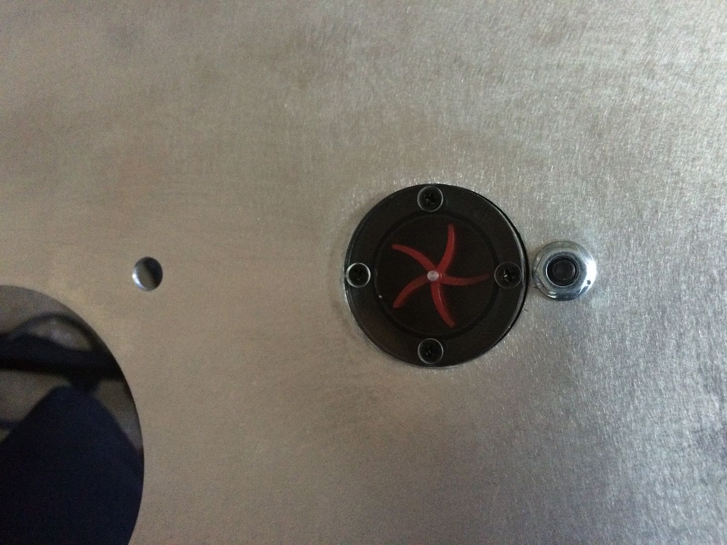
i decided to use the factory sending unit/cap for the tank, it is very easy to take off and on and will allow me to add coolant, check the level, etc... i cut the wire to it, and glued that also (not sure why i glued it, other than i felt like I just had to do somethin to it to complete it after cutting the plug off.. smh)..
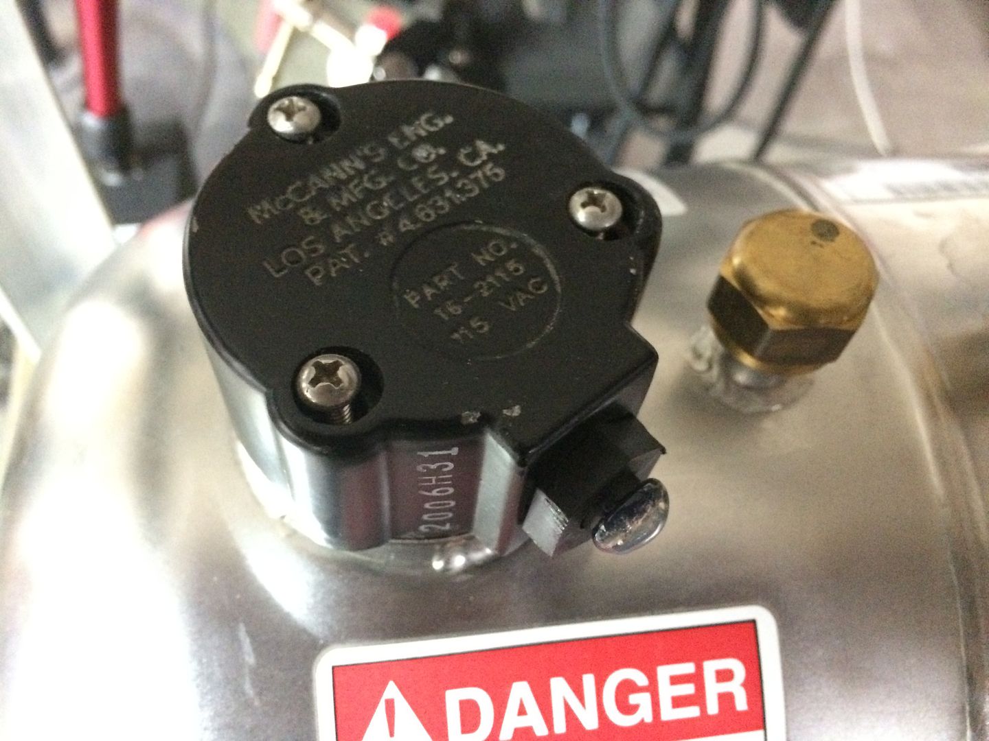
you remove the three phillips head screws, to access three studs and after taking those out... the unit pulls off easily... i can prob find a cap to fit n the area... but i dont intend to spend any money, where it would not add any reasonable benefit...
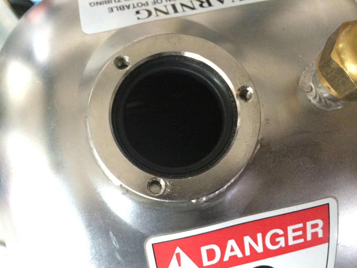
you remove the three phillips head screws, to access three studs and after taking those out... the unit pulls off easily... i can prob find a cap to fit n the area... but i dont intend to spend any money, where it would not add any reasonable benefit...
Last edited by LS Customs on Mon Aug 22, 2016 2:26 am, edited 4 times in total.
LS Customs
- LS Customs
-
Ace
-
Posts:
-
Joined:Tue Feb 23, 2016 11:56 pm
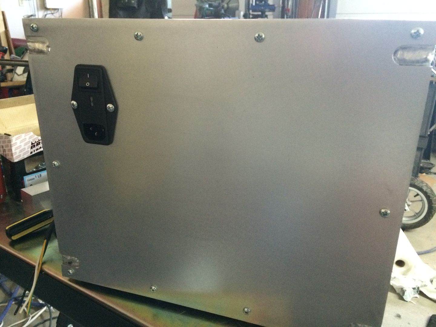
i installed the iec power module, on what I call the back of this setup. this is the panel, where i would add another fan inline with the front fan... if i feel it is needed to help keep the entire inside of the enclosure cooler.. the radiator and fan will no doubt bee enough to keep the coolant and torch cool (if working properly), but my intention here is to also keep the pumps motor as cool as possible... and a fan is very inexpensive, especially, compared to a motor...
in this pic, you can also see why i notched the sides.. the panel is able to sit flat... i would rather have smooth the welds, out, but i want this to be more functional, over cosmetic... and i also hope to get much better with the tig with practice... and seeing my earlier welds, will be sentimental to me, in that time..
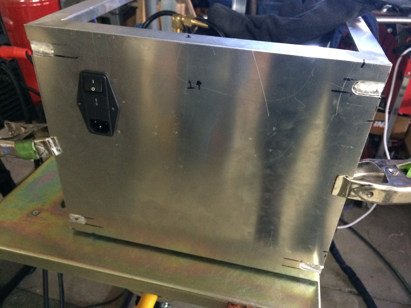
as you can see, the bac of the module, is well protected from any splatter, etc.. while filing the tank or checking the tank, etc... i dont see it being a problem where it is at... if there is a leak or any thing else... throughout the years..
in this pic, you can also see why i notched the sides.. the panel is able to sit flat... i would rather have smooth the welds, out, but i want this to be more functional, over cosmetic... and i also hope to get much better with the tig with practice... and seeing my earlier welds, will be sentimental to me, in that time..
as you can see, the bac of the module, is well protected from any splatter, etc.. while filing the tank or checking the tank, etc... i dont see it being a problem where it is at... if there is a leak or any thing else... throughout the years..
Last edited by LS Customs on Mon Aug 22, 2016 2:28 am, edited 2 times in total.
LS Customs
- LS Customs
-
Ace
-
Posts:
-
Joined:Tue Feb 23, 2016 11:56 pm
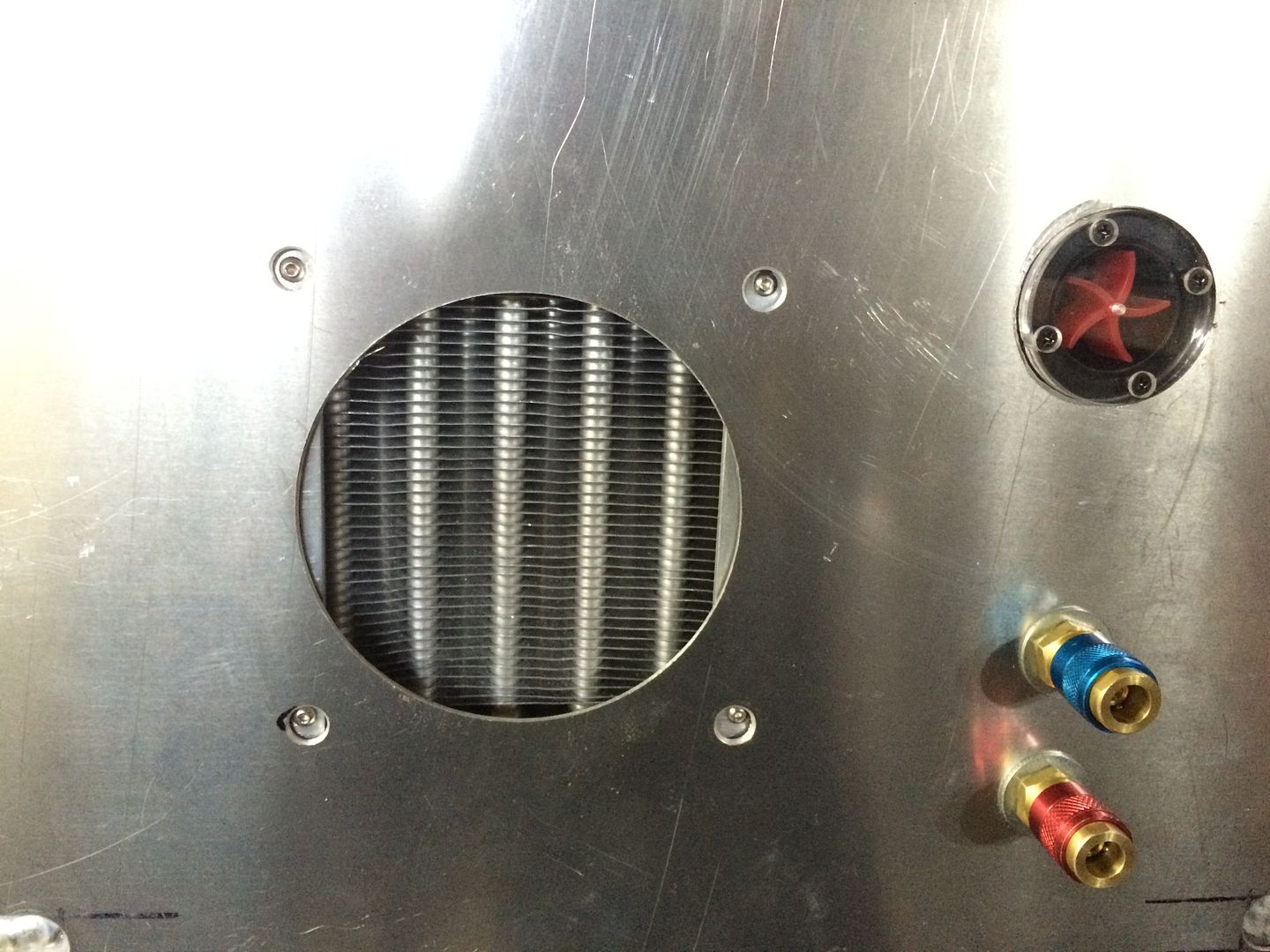
i marked some holes, etc... on what I am calling the front of this enclosure... and drilled these out... got the components test fit and am happy with fitment... I do have an actual pressure gauge and thought about mounting it on one the panels.. however, since i have to take a panel off to adjust the pressure, i will routinely check it from time to time, to make sure it is all working properly... i also have lexan or plexiglas laying around and can add a window on one of the panels, where i can peek though, if not seeing the pressure gauge bothers me at any point..
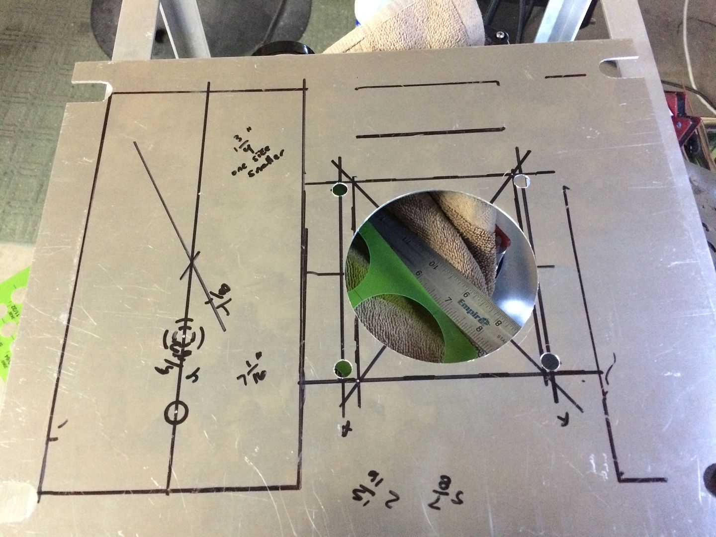
i drilled holes to clear the bolts for the radiator and fan also... the panels sit flat on all sides...
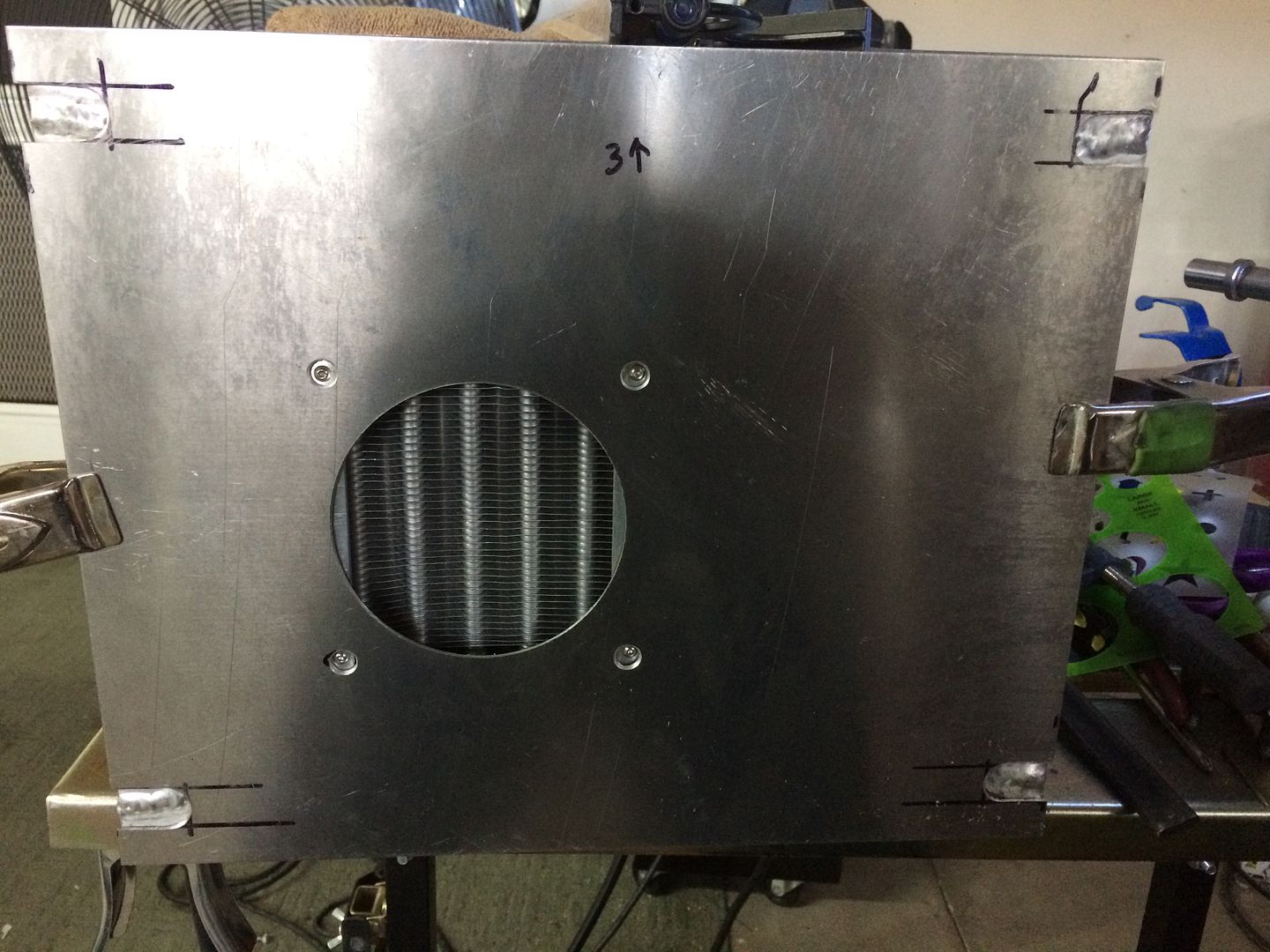
i drilled holes to clear the bolts for the radiator and fan also... the panels sit flat on all sides...


Looks very nice 
Not sure if you intend to already (looking at the amount of detail work, I assume I'm just being annoying here in mentioning this ), but just in case, please also run a ground wire from a stud on the case/frame to your ground pin on the power input so the whole case is grounded and protected from any accidental loose power cables in the housing.
Bye, Arno.
Not sure if you intend to already (looking at the amount of detail work, I assume I'm just being annoying here in mentioning this
Bye, Arno.
LS Customs
- LS Customs
-
Ace
-
Posts:
-
Joined:Tue Feb 23, 2016 11:56 pm
good sound logic, is never annoying to me... even if im wrong, or overlooked something...Arno wrote: please also run a ground wire from a stud on the case/frame to your ground pin on the power input so the whole case is grounded and protected from any accidental loose power cables in the housing.
Bye, Arno.
I did not add an additional ground, from the iec to the chassis... and took extra care to protect the wiring... on the outside of the box... something could fall on the wiring, socket, etc.. something could happen that I did not think about... and since u made this request/suggestion, I am not one to be arrogant and will not ignore this... thank you for your suggestion, it wont hurt anything to add it... i have 2 extra pins on those connectors...
LS Customs
- LS Customs
-
Ace
-
Posts:
-
Joined:Tue Feb 23, 2016 11:56 pm
thanks again for your input... took care of this...Arno wrote:please also run a ground wire from a stud on the case/frame to your ground pin on the power input so the whole case is grounded and protected from any accidental loose power cables in the housing.
Bye, Arno.
also laid out and pilot drilled all the holes for mounting the panels... this is the bottom... i pilot drilled and used self tapping sheet metal screws to attach the panels, to make sure all holes and panels lined up... its very secure, but i will more than likely add 10-24 rivet nuts and use 10-24 allen bolts, so that i will be able to take any panels off and on (for routine checks) without worrying about stripping the holes, etc... these screws may hold up just fine though... and are smaller than 10-24s
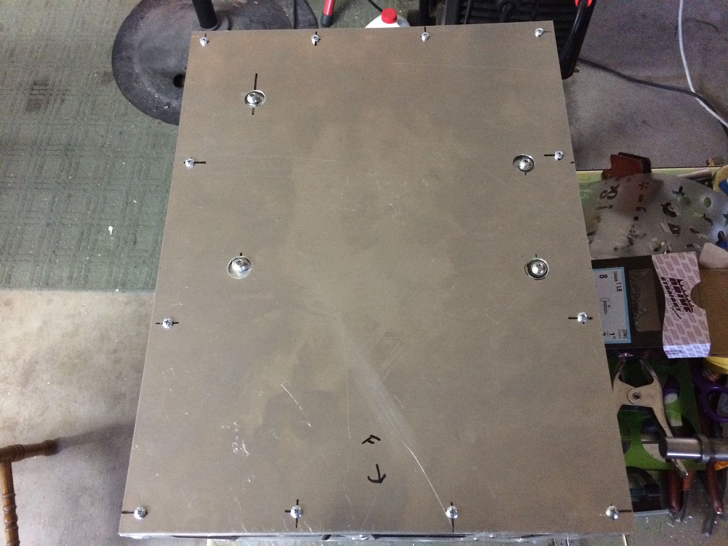
working on getting it all, either tonight, or in the morning... will add some texture of some sort to the outside of the panels, and then test it all out...
LS Customs
- LS Customs
-
Ace
-
Posts:
-
Joined:Tue Feb 23, 2016 11:56 pm
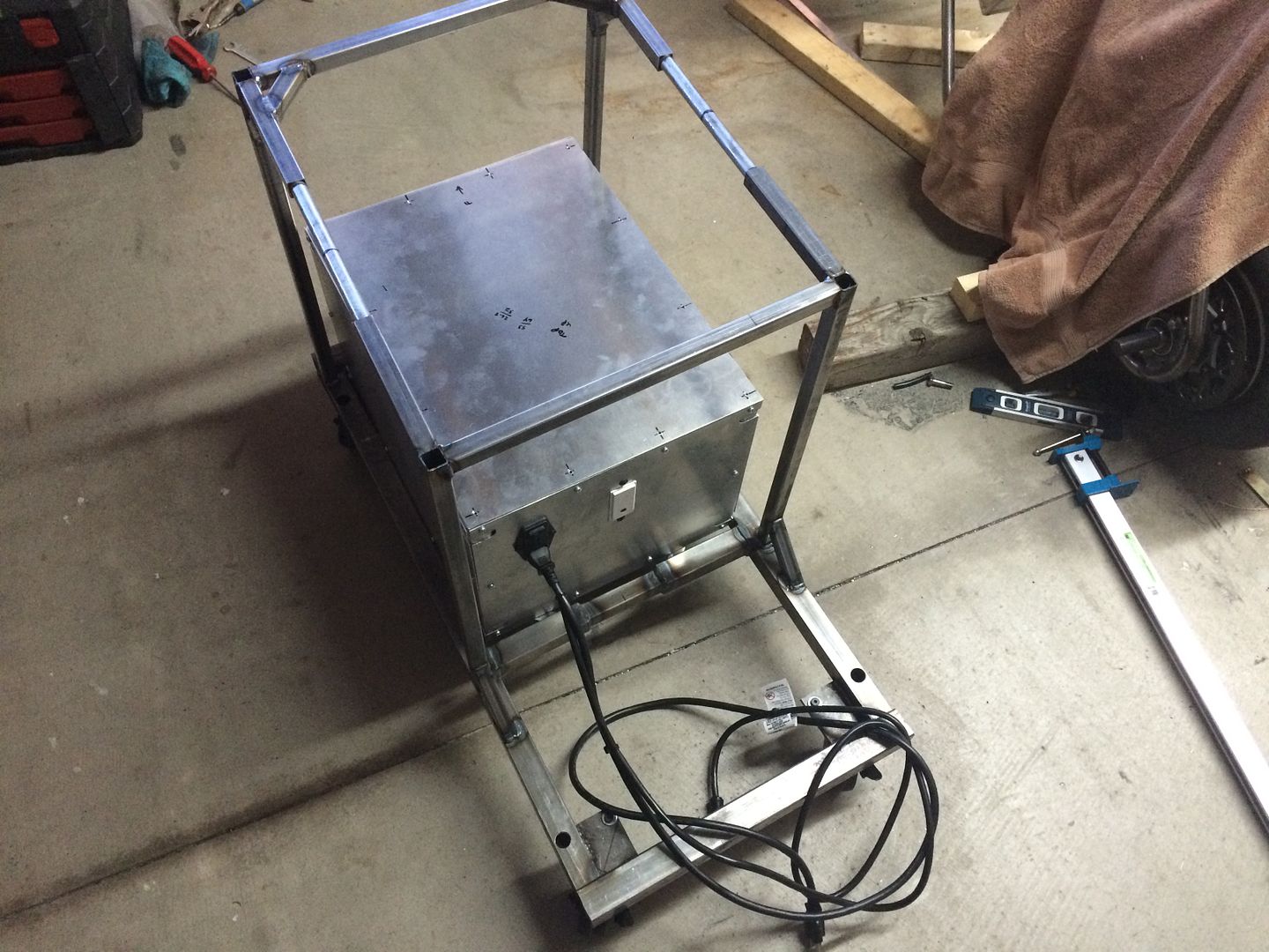
as I put this back together, I am playing with textures/sanding, etc on the panels.. i like the brushed look, but it is a pain for me to do right now.. so just hitting it with a da and calling it a day... if i take this apart at some point, i will try to clean it up real nice... but main point was to get any notable scratches and marks off of the panels..
got the iec mounted and all wiring finalized and ran away from the motor...
got the iec mounted and all wiring finalized and ran away from the motor...
LS Customs
- LS Customs
-
Ace
-
Posts:
-
Joined:Tue Feb 23, 2016 11:56 pm
I used ARP thread sealant on all the threads that were not flare fittings... i was going to use this plastic filter, but it broke pretty easily as i was trying to clock the cap for the filter, so that i could get to it, without moving the filter in the future... smh!
in this pic, the other fittings have not been tightened, and so it looks like there is excess thread sealant, but excess was wiped off after tightening... anyhow... had to throw this filter away...
I ordered the filter I intended to use in the first place... and this will be installed, on the return line of the torch, with the quick connect and snap into the cooler quick connect... so i continued to plumb the lines...
LS Customs
- LS Customs
-
Ace
-
Posts:
-
Joined:Tue Feb 23, 2016 11:56 pm
to mount the flow sight, it didnt have a way to mount it, so i drilled a hole where clear on the top.. and used a bolt and nut to secure it to the panel

only problem, is they sent it with the wrong size fitting... 3/8" ID and im using 1/4" ID everywhere else... and while im eager to get this tested, im already waiting on the new filter to arrive.. so i just ordered the correct size fittings.. instead of using the cheap plastic adapters... id rather all the lines be the same ID anyway...
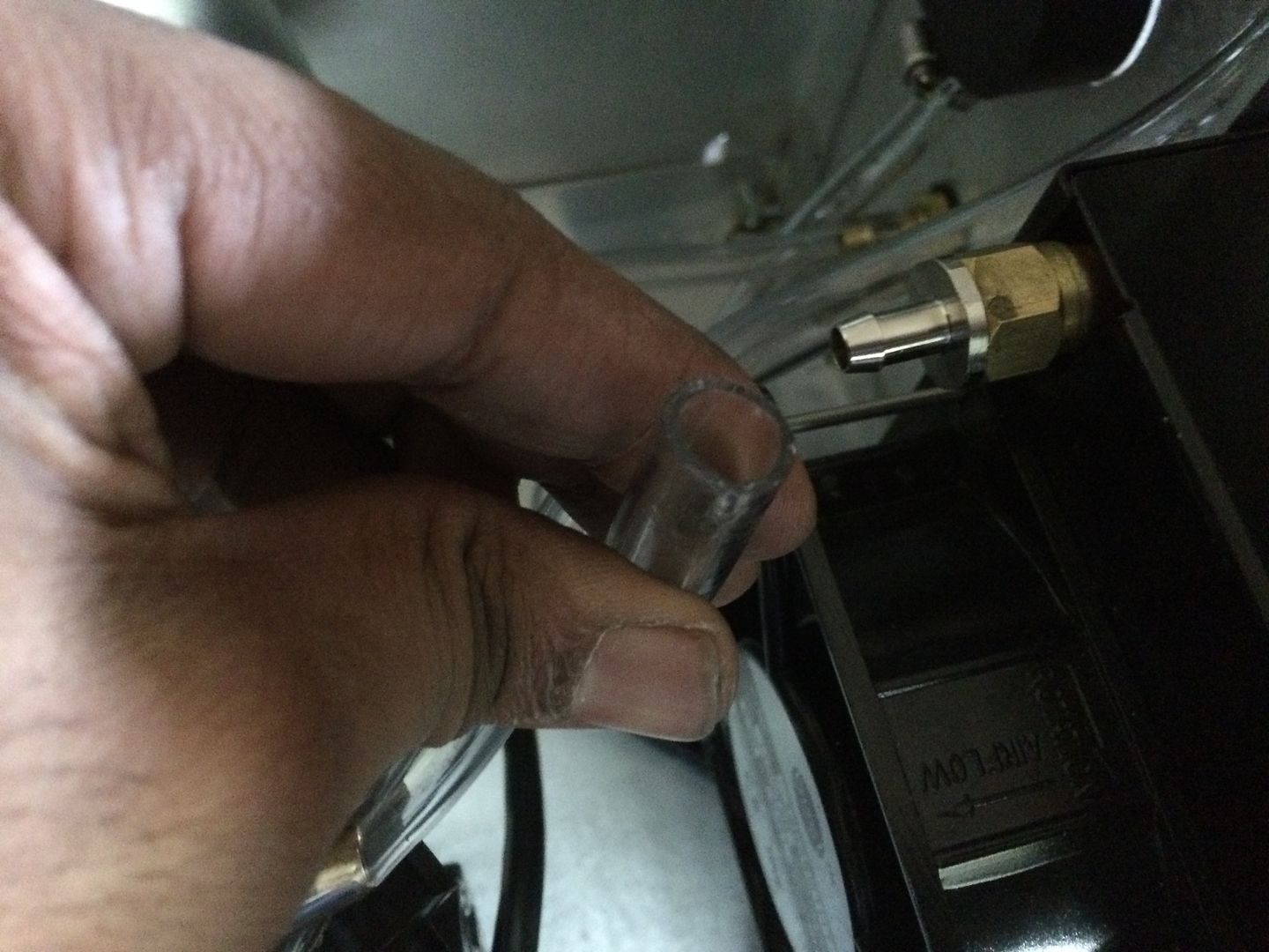
only problem, is they sent it with the wrong size fitting... 3/8" ID and im using 1/4" ID everywhere else... and while im eager to get this tested, im already waiting on the new filter to arrive.. so i just ordered the correct size fittings.. instead of using the cheap plastic adapters... id rather all the lines be the same ID anyway...
LS Customs
- LS Customs
-
Ace
-
Posts:
-
Joined:Tue Feb 23, 2016 11:56 pm
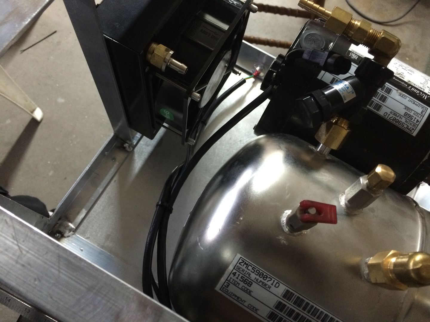
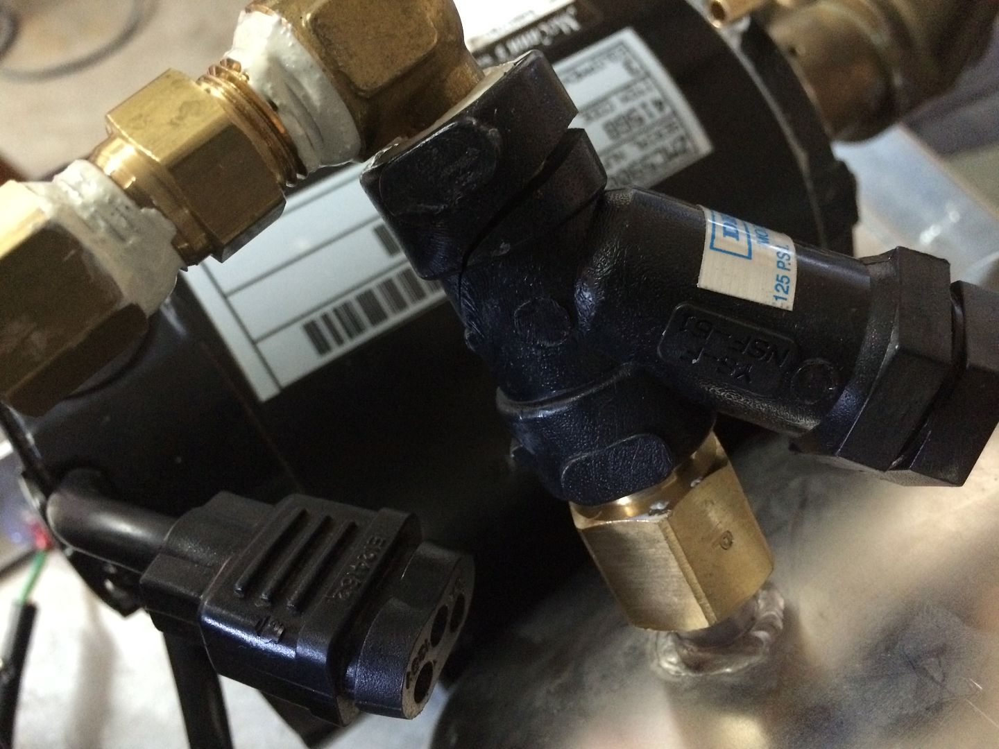
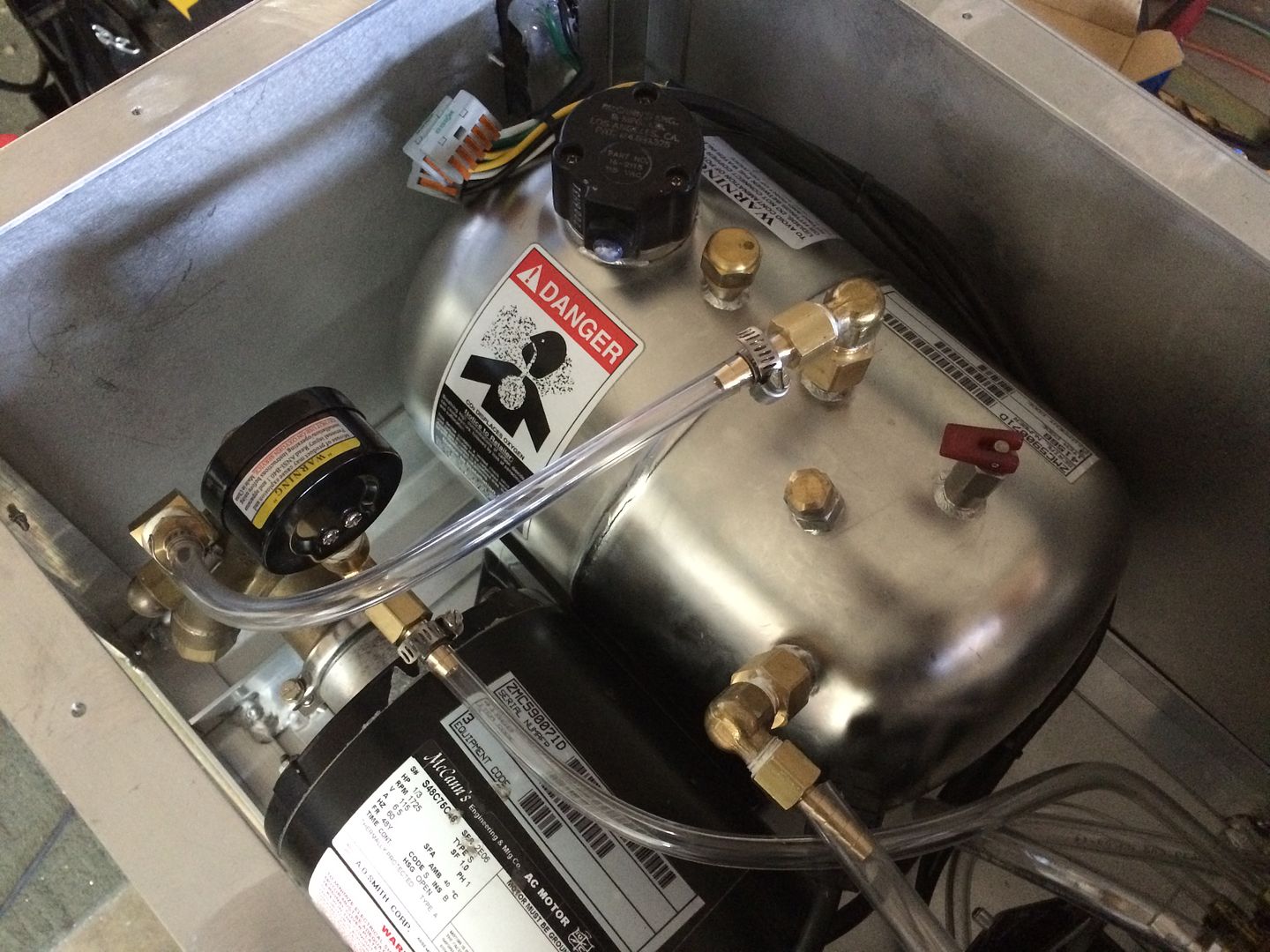
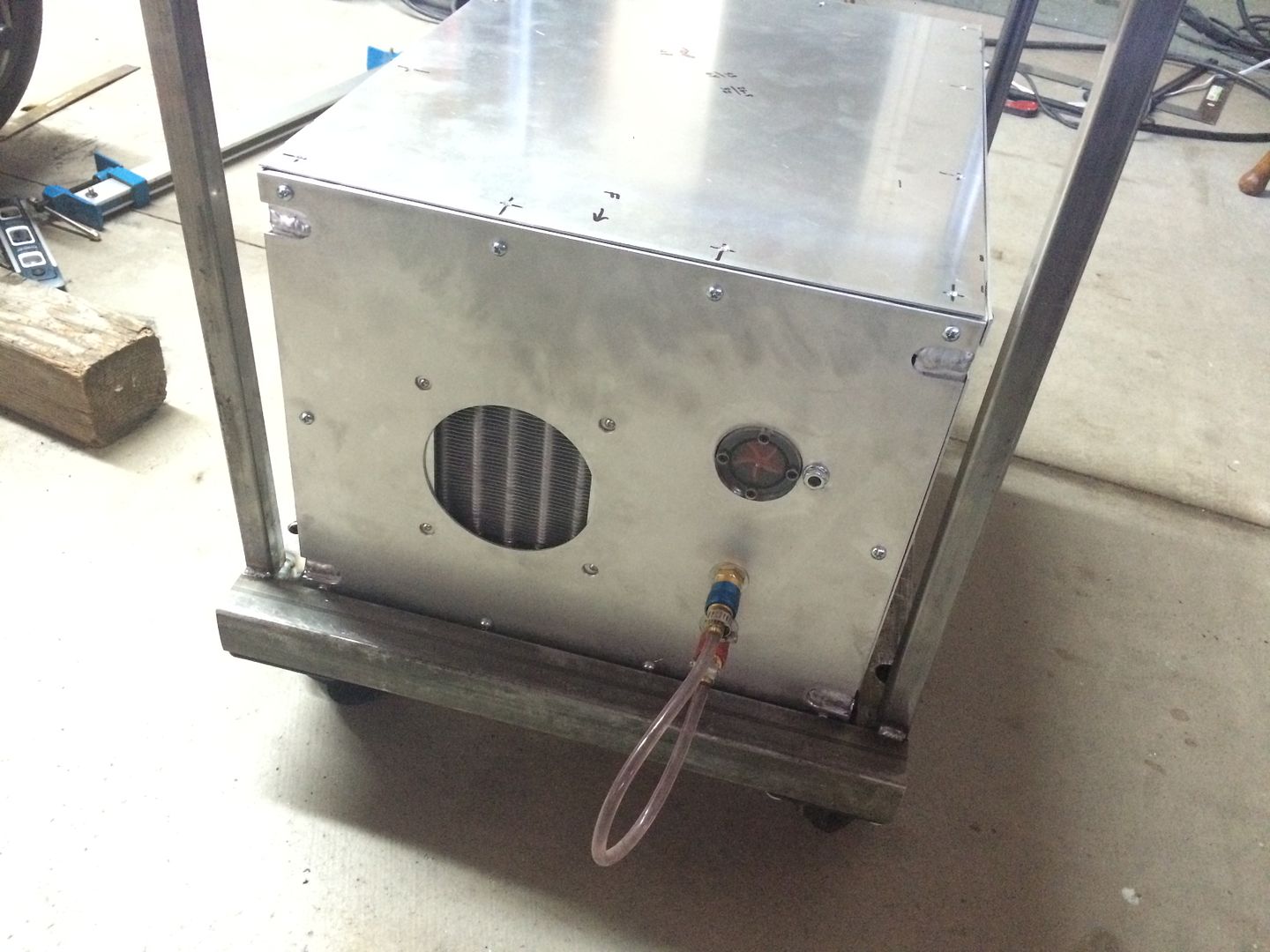
everything else all plumbed and ready to go... used all stainless hose clamps on the hoses...
in from the red quick connect (coming from the hot side of the torch), to one side of the radiator and out from the radiator to the flow sight... (because I would like to "see" that the coolant is flowing nicely all the way through the torch, as opposed to before the torch)... from the flow sight to the tank...
the thicker/odd looking lines from the sight to the radiator/tank are just shoved on the other ends, to keep my train of thought, but will be ran nicely, when the correct fittings arrive...
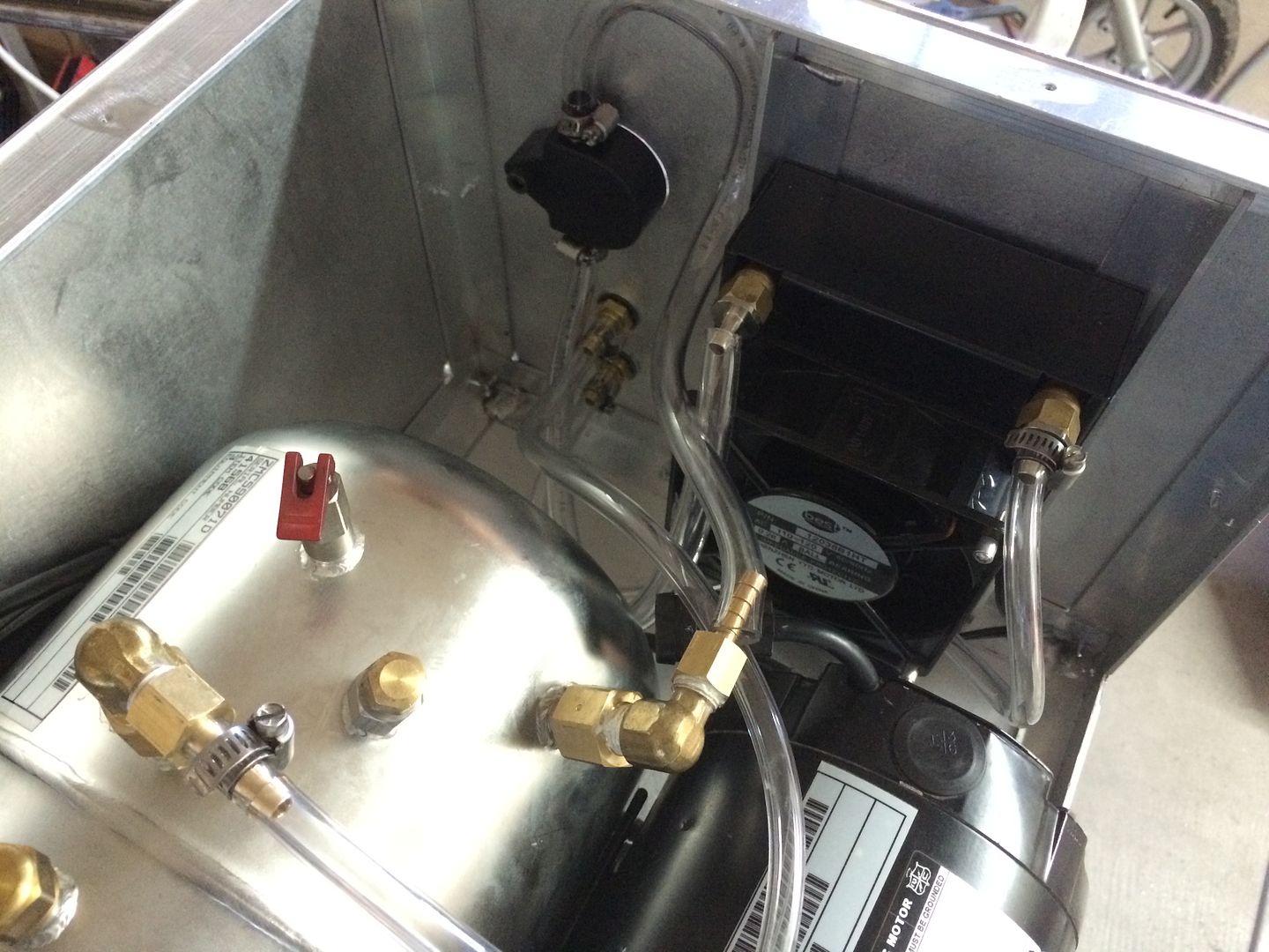
made sure the lines do not touch the motor, in case it happens to retain any heat, etc...
the out from the pump, goes through the adjustable valve and the pressure gauge (after the valve) and to the input/cool quick connect for the torch)...
in from the red quick connect (coming from the hot side of the torch), to one side of the radiator and out from the radiator to the flow sight... (because I would like to "see" that the coolant is flowing nicely all the way through the torch, as opposed to before the torch)... from the flow sight to the tank...
the thicker/odd looking lines from the sight to the radiator/tank are just shoved on the other ends, to keep my train of thought, but will be ran nicely, when the correct fittings arrive...
made sure the lines do not touch the motor, in case it happens to retain any heat, etc...
the out from the pump, goes through the adjustable valve and the pressure gauge (after the valve) and to the input/cool quick connect for the torch)...
LS Customs
- LS Customs
-
Ace
-
Posts:
-
Joined:Tue Feb 23, 2016 11:56 pm
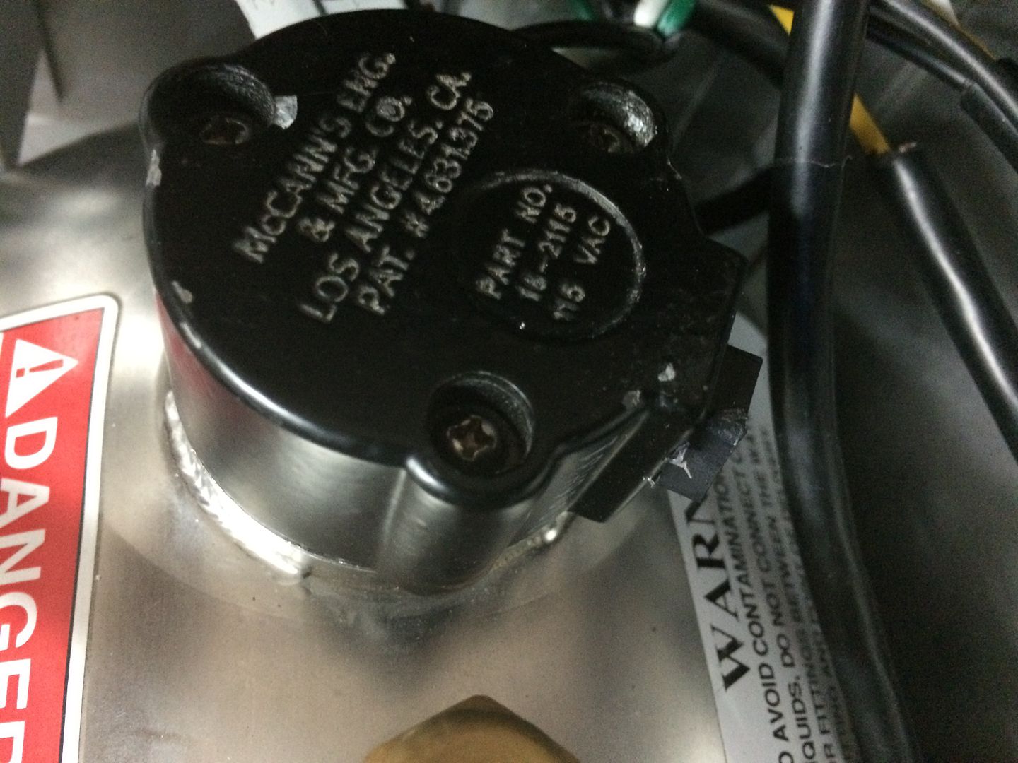
tested the motor... doesnt like that iec plug/fuse setup... blew the fuses, while trying to prime... wired it to its own plug... and had no issues... going to be adding a switch for it, separate from the fan, or one that can handle both... glad it seems to work nicely... i would like to change this fan out for one that can flow more air/faster... the motor does seem to generate a bit of heat...
I guess you're basically at 'Version 0.0001-pre-alpha' at the moment.. 
Usually the devil is in the detail and in the modifications/changes that turn out to be needed once you actually start using it and go "Hmmm.. Perhaps that original idea wasn't so great and I should change this...". Can be a tedious and sometimes frustrating process, but all part of the development cycle. Keep at it and in the end it will be 'just right' for you!
Bye, Arno.
LS Customs
- LS Customs
-
Ace
-
Posts:
-
Joined:Tue Feb 23, 2016 11:56 pm
had a switch laying around... got the pump wired up separately... and the iec fuse had blown, intially i thought the fan was on... but it was actually spinning from the exhaust on the back of the motor... replaced the fuse and it is running nicely... ran it for 30 minutes, no leaks or issues... going to add the better fan and move this one to the top of the enclosure to help circulate the air...
LS Customs
- LS Customs
-
Ace
-
Posts:
-
Joined:Tue Feb 23, 2016 11:56 pm
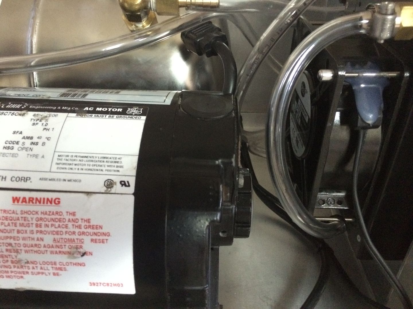
also, as i disconnected the float/reed switch on the tank, i by passed it... so that the pump turns on and off by the switch and is not dependent upon the level of coolant in the tank... i will check the level during any maintenance or future inspections
one end of plug on the pump
 \
\
other side of plug.. ran the green and yellow to the ground... and these two wires together, as this was going the reed switch and not color coded... by looking at the wiring under the cover on the motor, i was able to easily determine how the switch was wired...
that end went into this... which is a reed switch/float setup
one end of plug on the pump
\other side of plug.. ran the green and yellow to the ground... and these two wires together, as this was going the reed switch and not color coded... by looking at the wiring under the cover on the motor, i was able to easily determine how the switch was wired...
that end went into this... which is a reed switch/float setup
LS Customs
- LS Customs
-
Ace
-
Posts:
-
Joined:Tue Feb 23, 2016 11:56 pm
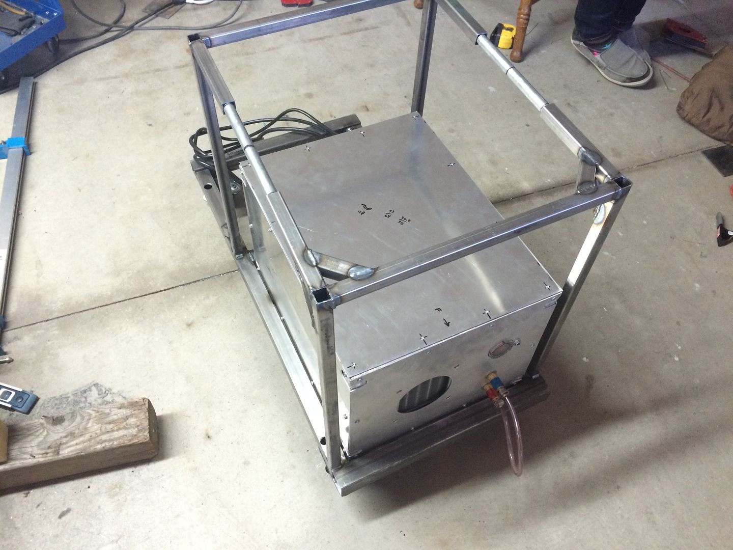
with that sorted... started on making a welding cart... using scrap... i had purchased casters to build one a while ago.. just put together as i went along... i want to add a drawer to it... going to put two tanks (one argon, one helium) and add pvc tubing for filler wire (like Jody has shown in one of his vids)...
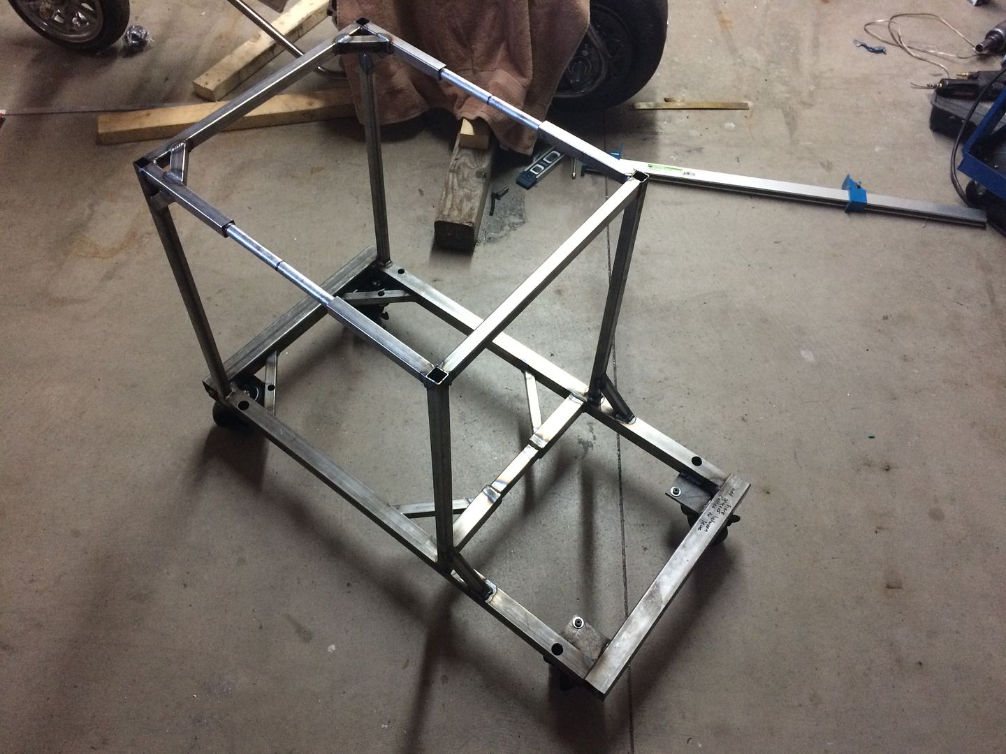
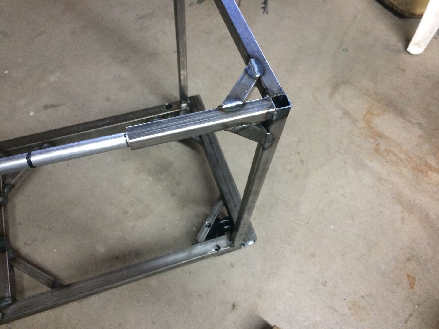
Last edited by LS Customs on Sun Sep 04, 2016 8:06 pm, edited 1 time in total.
LS Customs
- LS Customs
-
Ace
-
Posts:
-
Joined:Tue Feb 23, 2016 11:56 pm
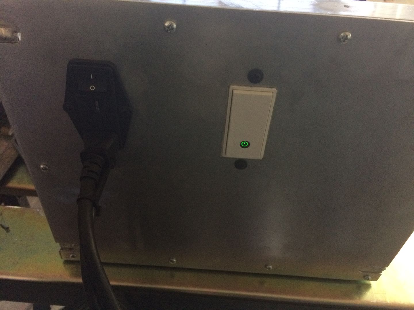
i can turn the water cooler setup on and off with my iphone... not that i need to or would... just that the switch works that way... lol
Return to “Welding Projects - Welding project Ideas - Welding project plans”
Jump to
- Introductions & How to Use the Forum
- ↳ Welcome!
- ↳ Member Introductions
- ↳ How to Use the Forum
- ↳ Moderator Applications
- Welding Discussion
- ↳ Metal Cutting
- ↳ Tig Welding - Tig Welding Aluminum - Tig Welding Techniques - Aluminum Tig Welding
- ↳ Mig and Flux Core - gas metal arc welding & flux cored arc welding
- ↳ Stick Welding/Arc Welding - Shielded Metal Arc Welding
- ↳ Welding Forum General Shop Talk
- ↳ Welding Certification - Stick/Arc Welding, Tig Welding, Mig Welding Certification tests - Welding Tests of all kinds
- ↳ Welding Projects - Welding project Ideas - Welding project plans
- ↳ Product Reviews
- ↳ Fuel Gas Heating
- Welding Tips & Tricks
- ↳ Video Discussion
- ↳ Wish List
- Announcements & Feedback
- ↳ Forum News
- ↳ Suggestions, Feedback and Support
- Welding Marketplace
- ↳ Welding Jobs - Industrial Welding Jobs - Pipe Welding Jobs - Tig Welding Jobs
- ↳ Classifieds - Buy, Sell, Trade Used Welding Equipment
- Welding Resources
- ↳ Tradeshows, Seminars and Events
- ↳ The Welding Library
- ↳ Education Opportunities