Along with trying to make a tig torch cooler (http://forum.weldingtipsandtricks.com/v ... f=9&t=9049), I also decided to try to make a rotary welding positioner. I wanted to grab one of the ones Ive seen in one of Jody's vids, but they are too expensive for me to justify it at this time... I am fairly new to tig welding, but I am doing things to help pay for the materials, etc. I a comfortable with the practice already, but I need to practice as often as I can.
I figured I would post it as I go along... I have a couple of friends that would like for me to put together sort of a "kit" for them too use also, so Im hoping this works very well... I have never done anything like this before, so feel free to criticize (constructively)... or offer your opinions... thanks...
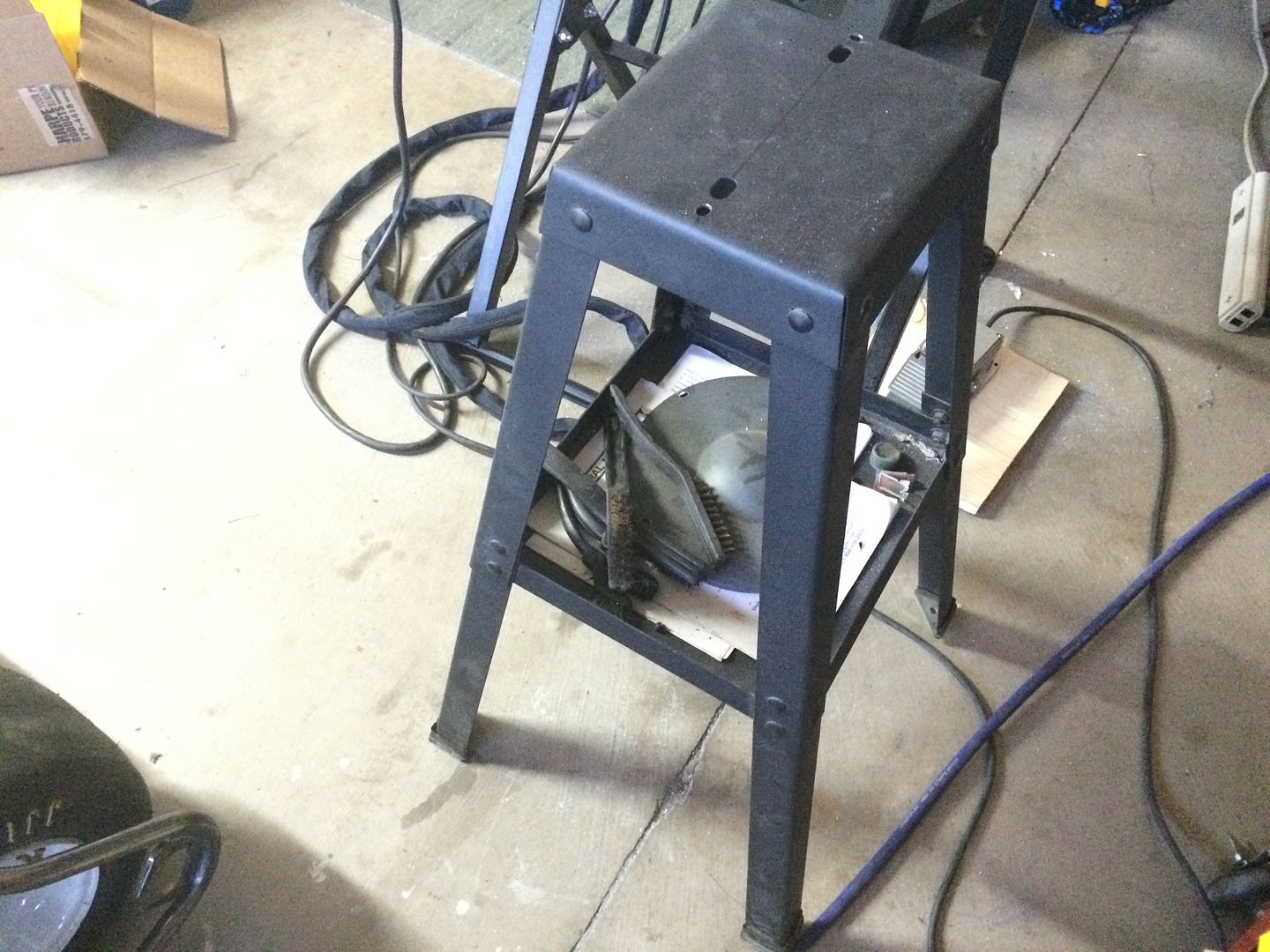
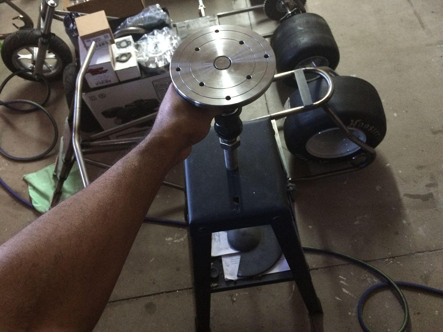
I am going to be adding a motor and pedal to this, but I can also use it and spin it by hand, if I make some sort of clamp for the torch... will be able to use this horizontally or vertically or in between... i am going to be making two of them, initially, and one does not need to tilt at this point, so i decided to use a cheap harbor freight tool stand (i already had laying around to mount everything to).
for this first one, I only need to be able to weld up to 6" ish tubing.. mainly 4" or smaller...
What welding projects are you working on? Are you proud of something you built?
How about posting some pics so other welders can get some ideas?
How about posting some pics so other welders can get some ideas?
LS Customs
- LS Customs
-
Ace

-
Posts:
-
Joined:Tue Feb 23, 2016 11:56 pm
Here are some of the parts, I have gathered so far...
the stand... they do have one that is more "heavy duty" but I dont need to get it... and i will be laser cutting some 1/8" pieces and making them puzzle piece together to make the bench top version... I am a home hobbyist.. I program my own parts and then have friends where they either cnc my programs, or i can operate the laser myself (i learned this a while ago to save money)...
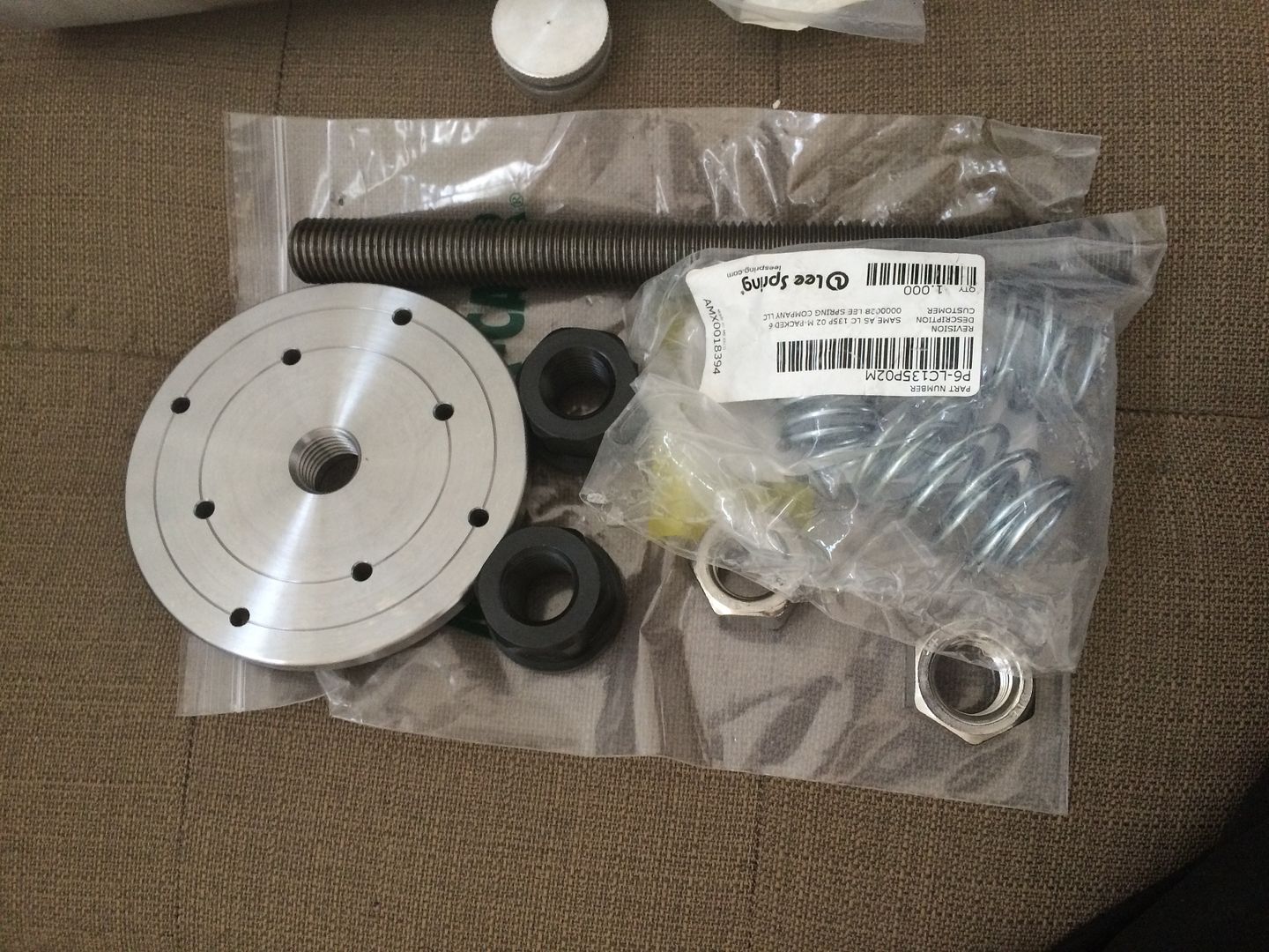
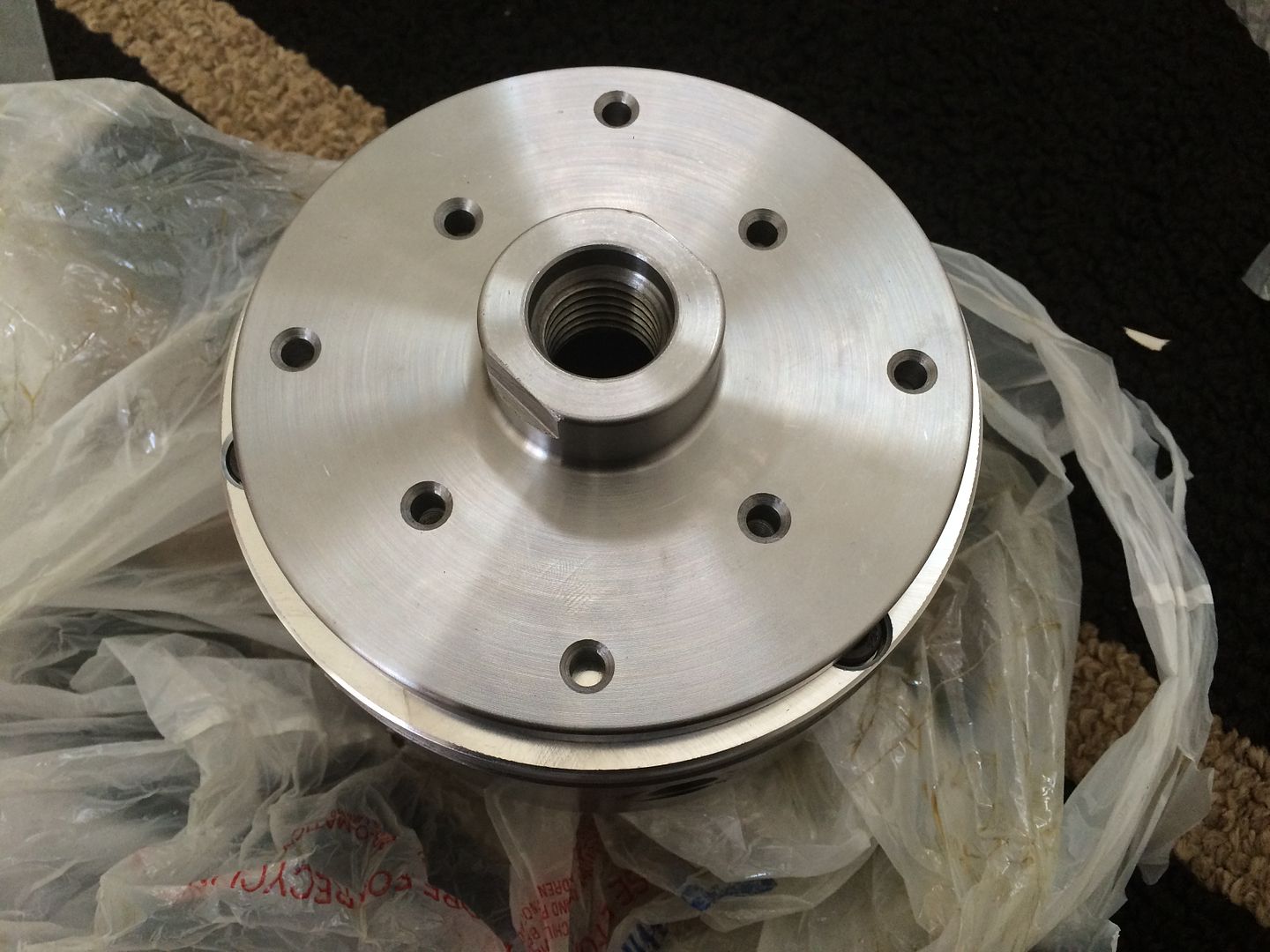
there are plenty of lathe plates on ebay and in aluminum, cast iron, or steel... I got the steel one, so that i could use magnets if need be... this particular plate has a threaded hole 1"-8.
the stand... they do have one that is more "heavy duty" but I dont need to get it... and i will be laser cutting some 1/8" pieces and making them puzzle piece together to make the bench top version... I am a home hobbyist.. I program my own parts and then have friends where they either cnc my programs, or i can operate the laser myself (i learned this a while ago to save money)...
there are plenty of lathe plates on ebay and in aluminum, cast iron, or steel... I got the steel one, so that i could use magnets if need be... this particular plate has a threaded hole 1"-8.
LS Customs
- LS Customs
-
Ace
-
Posts:
-
Joined:Tue Feb 23, 2016 11:56 pm
I picked up a few nuts, two flanged and two to lock things down if need be (I also have locking collars around, as i use those routinely)... and a spring (came with 5 in the package, only using one)...
LS Customs
- LS Customs
-
Ace
-
Posts:
-
Joined:Tue Feb 23, 2016 11:56 pm
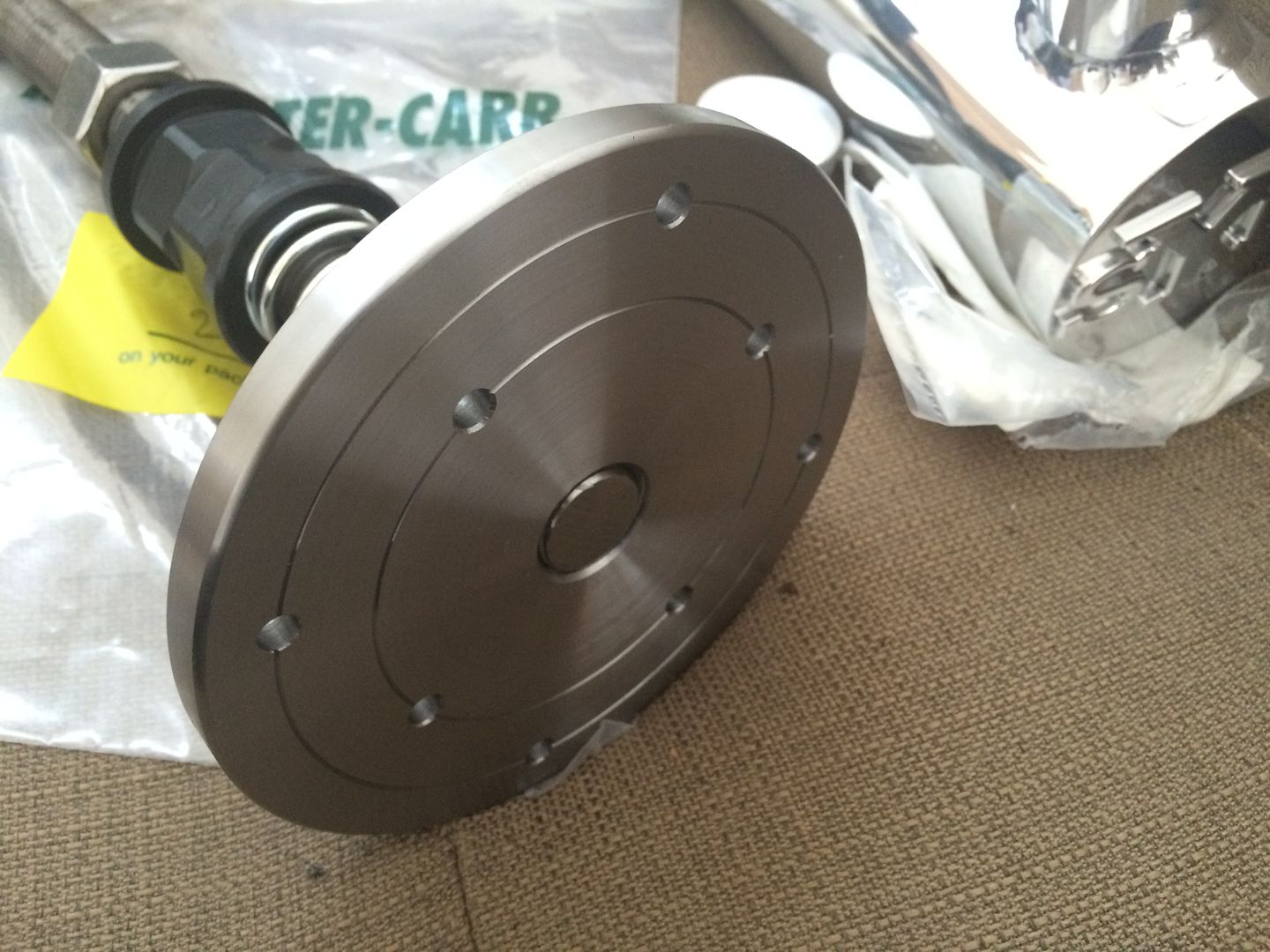
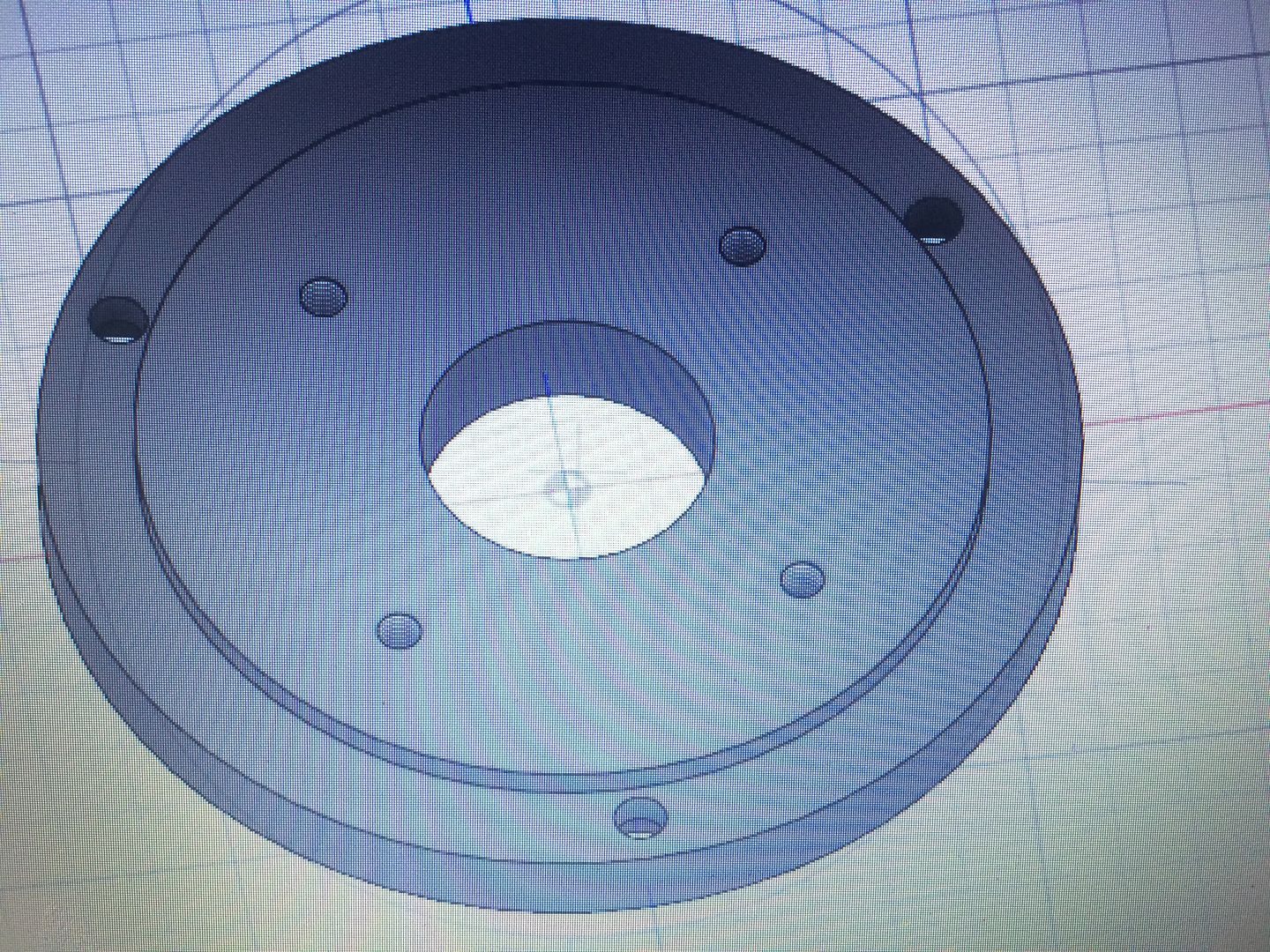
these are the two pieces i programmed and will be solid copper... I figured that most have problems with the ground... so i wanted the pieces to be copper (thinking that it would be best for attaching the ground?)
this piece screws directly into the bottom of the circle plate... i added some flats on the sides to get a wrench on it if i want... the thread is long enough (1.187") for the top of the part to sit flush with this table... and the bottom of my adapter allows for .75" (wasnt sure of how much thread i needed so gave it plenty) of shaft to be threaded into it ...
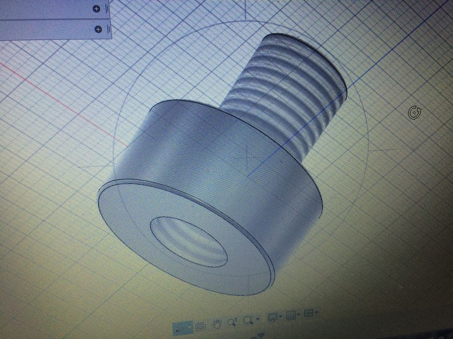
this piece screws directly into the bottom of the circle plate... i added some flats on the sides to get a wrench on it if i want... the thread is long enough (1.187") for the top of the part to sit flush with this table... and the bottom of my adapter allows for .75" (wasnt sure of how much thread i needed so gave it plenty) of shaft to be threaded into it ...
LS Customs
- LS Customs
-
Ace
-
Posts:
-
Joined:Tue Feb 23, 2016 11:56 pm
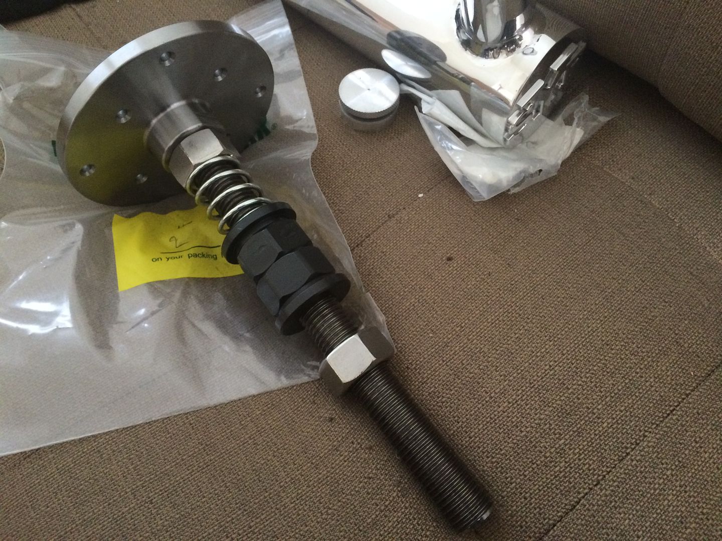
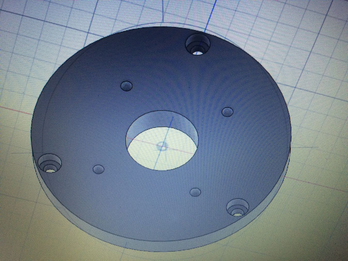
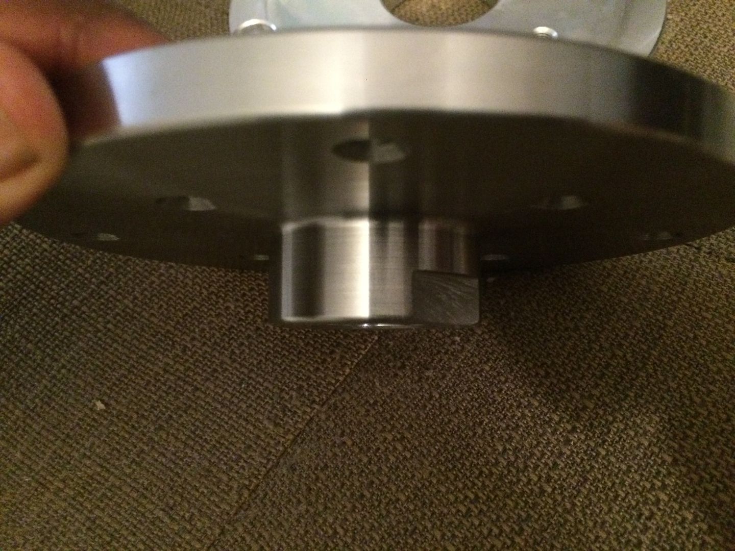
i am going to use this piece to press against the copper adapter, but will be able to spin against it... and the ground cable from the welder will attach to it
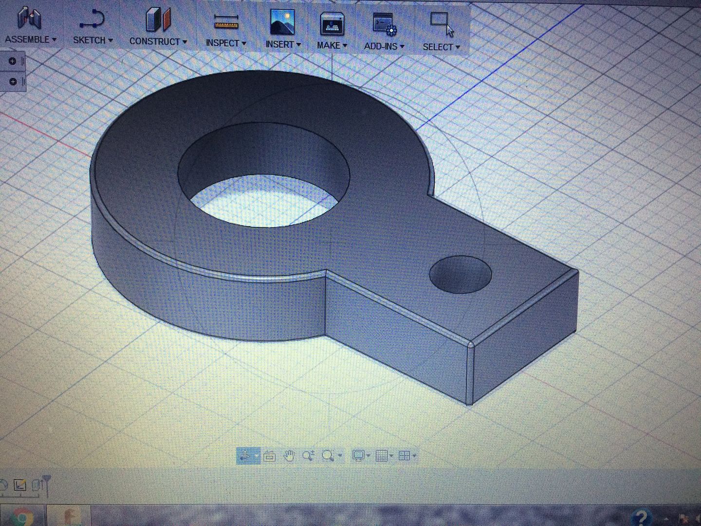
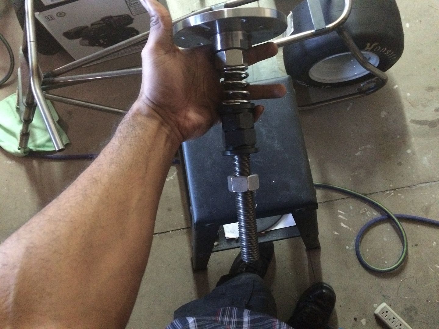
the spring will keep pressure on the bottom of this piece... and thought the two pieces will rub together, they should last for the life of the machine (?) I dont see it wearing down much at all, but thats why i put the spring... the spring tension can be adjusted by one of the flanged nuts, like in the picture.
where the silver colored nut is (against the bottom of the plate), the adaptor and the ground lug will be...
Last edited by LS Customs on Fri Feb 26, 2016 12:35 am, edited 1 time in total.
LS Customs
- LS Customs
-
Ace
-
Posts:
-
Joined:Tue Feb 23, 2016 11:56 pm
will use a bearing on the top of the stand and the ground setup will be above this bearing... was looking for a tapered bearing or one that would work for both axial and radial... but i have these laying around too not sure if these are fine for the limited amount of weight that will be on the table... they have cassettes and i believe have some support axially? i still havent looked into info on this style of bearing...
but will mount a bearing on top... and then one or two below, modding the lower half to house the motor and bearings, sprockets/pulley, or whatever i will use to attach the motor... just havent found a motor yet... once found, i can easily attached a pulley or sprocket to the shaft... and weld in mounts for everything under the stand...
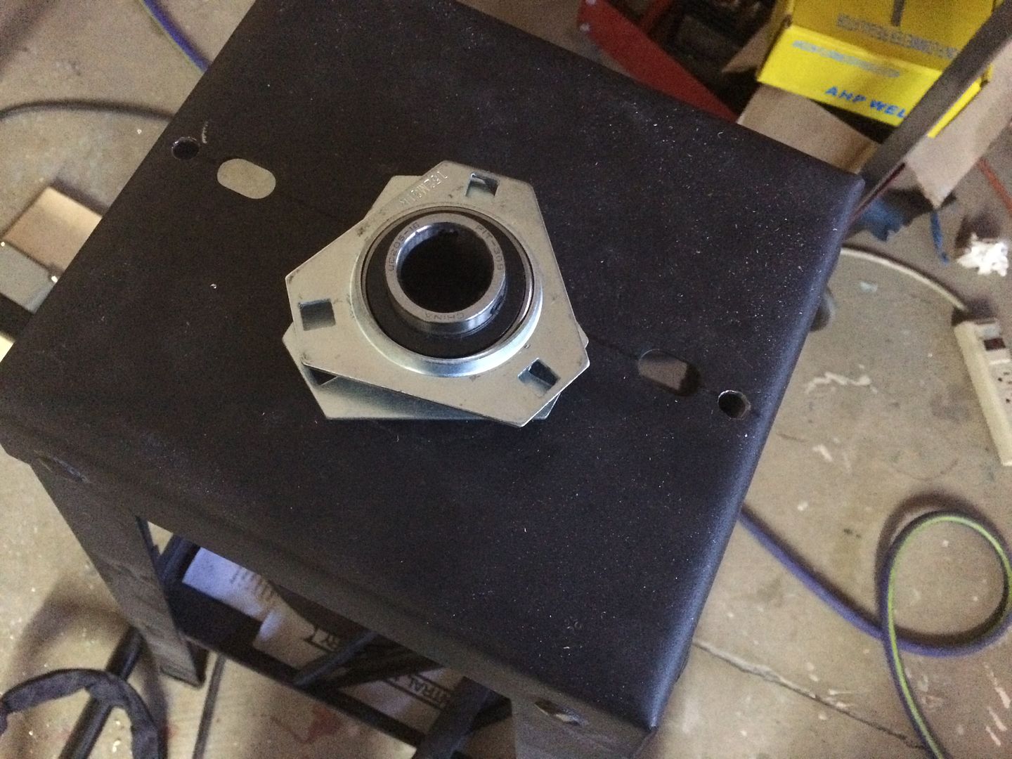
but will mount a bearing on top... and then one or two below, modding the lower half to house the motor and bearings, sprockets/pulley, or whatever i will use to attach the motor... just havent found a motor yet... once found, i can easily attached a pulley or sprocket to the shaft... and weld in mounts for everything under the stand...
LS Customs
- LS Customs
-
Ace
-
Posts:
-
Joined:Tue Feb 23, 2016 11:56 pm
im am putting the ground above the top bearing closest to the plate and will be able to lock the clamp from the welder and lug down easily and also was thinking any current wouldn't be able to travel all the way down the shaft and through the bearings?.. etc...
but if need be, i can use a bearing with a larger id than the 1"... then program a bushing (out of plastic? or some other material that wont let current travel through it) this would sit on the bearing and the shaft would go though it without touching the bearings...
the current should be fine the way im am grounding this, right, without having to use insulate the bearings? i have a tendency to do more than what is necessary, when i am not comfortable or familiar with something...
GreinTime
- GreinTime
-
Weldmonger

-
Posts:
-
Joined:Fri Nov 01, 2013 11:20 am
-
Location:Pittsburgh, PA
Technically yes, the ground would be fine where it's at, although I also like your idea of the bushings to insulate the bearing shaft as well. Current takes the path of least resistance, so you should 'in theory' be fine, but over engineering typically doest hurt anything but the bank account!
The whole project, and your water cooler, are well thought out. I appreciate the attention to detail and hope to see the finished product.
Sent from my SM-G900V using Tapatalk
The whole project, and your water cooler, are well thought out. I appreciate the attention to detail and hope to see the finished product.
Sent from my SM-G900V using Tapatalk
#oneleggedproblems
-=Sam=-
-=Sam=-
LS Customs
- LS Customs
-
Ace
-
Posts:
-
Joined:Tue Feb 23, 2016 11:56 pm
thank you... I have surgery next week (3rd), so trying to get this one going as best i can before that. but am going to make two, this one and try to make one that tilts.. i will use some bushings in that one to protect the bearings.. i picked up the copper today..GreinTime wrote:Technically yes, the ground would be fine where it's at, although I also like your idea of the bushings to insulate the bearing shaft as well. Current takes the path of least resistance, so you should 'in theory' be fine, but over engineering typically doest hurt anything but the bank account!
The whole project, and your water cooler, are well thought out. I appreciate the attention to detail and hope to see the finished product.
Sent from my SM-G900V using Tapatalk
Awesome, I've wanted to do this for awhile myself. Great build with well thought out issues!
I weld stainless, stainless and more stainless...Food Industry, sanitary process piping, vessels, whatever is needed, I like to make stuff.
ASME IX, AWS 17.1, D1.1
Instagram #RNHFAB
ASME IX, AWS 17.1, D1.1
Instagram #RNHFAB
LS Customs
- LS Customs
-
Ace
-
Posts:
-
Joined:Tue Feb 23, 2016 11:56 pm
Well... thought I would jump back on some of my projects... the surgery recovery, has been crazy.. but seeing the light of day! Have been fighting cancer for over a year now... and was in a very bad situation... this was hopefully the last of 3 major surgeries I had following the conventional treatment plan for my fight... things have gone as well as they could, though with complications. The most important thing is that I am now cancer free... just need to fight the side effects of treatment/recover and keep up the fight, so that I am doing everything in my power to keep it from coming back... anyhow...
back to some of these projects...
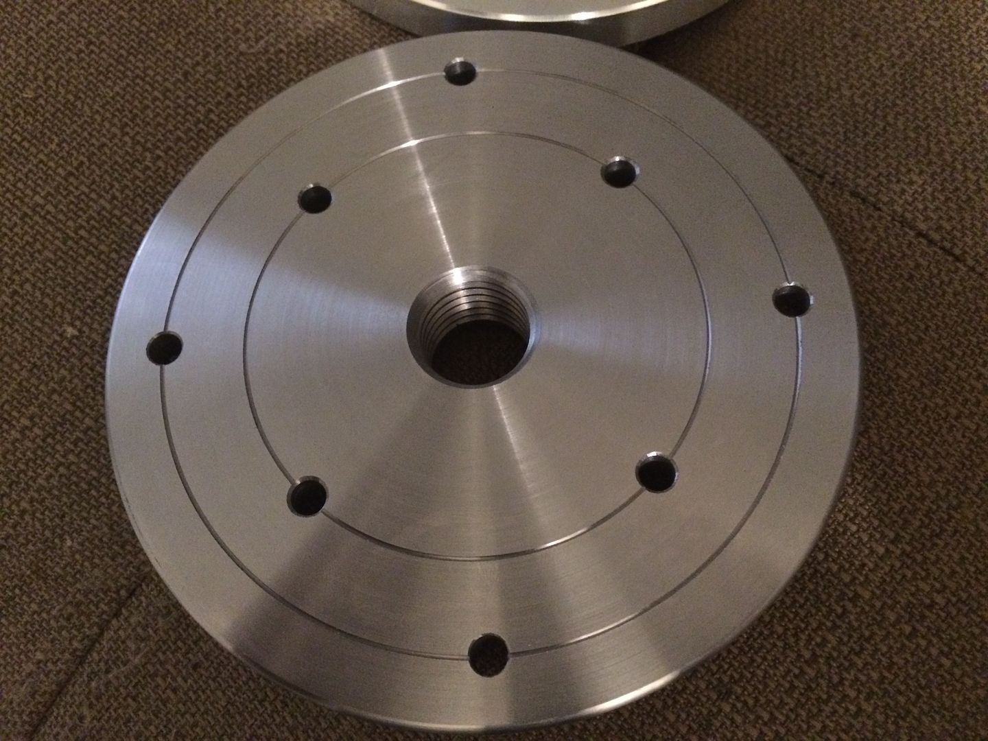
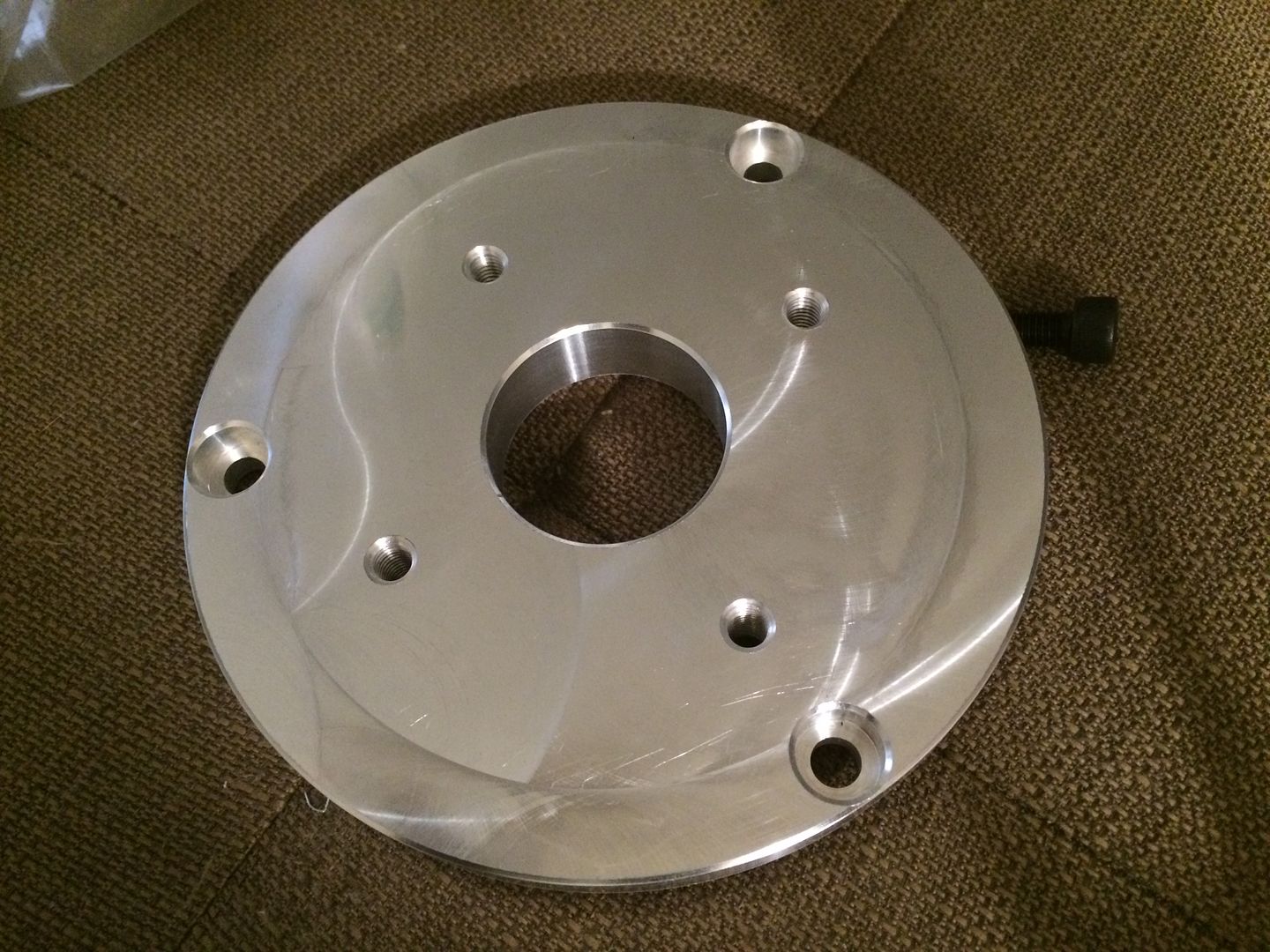
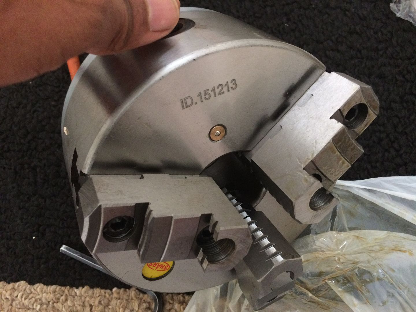
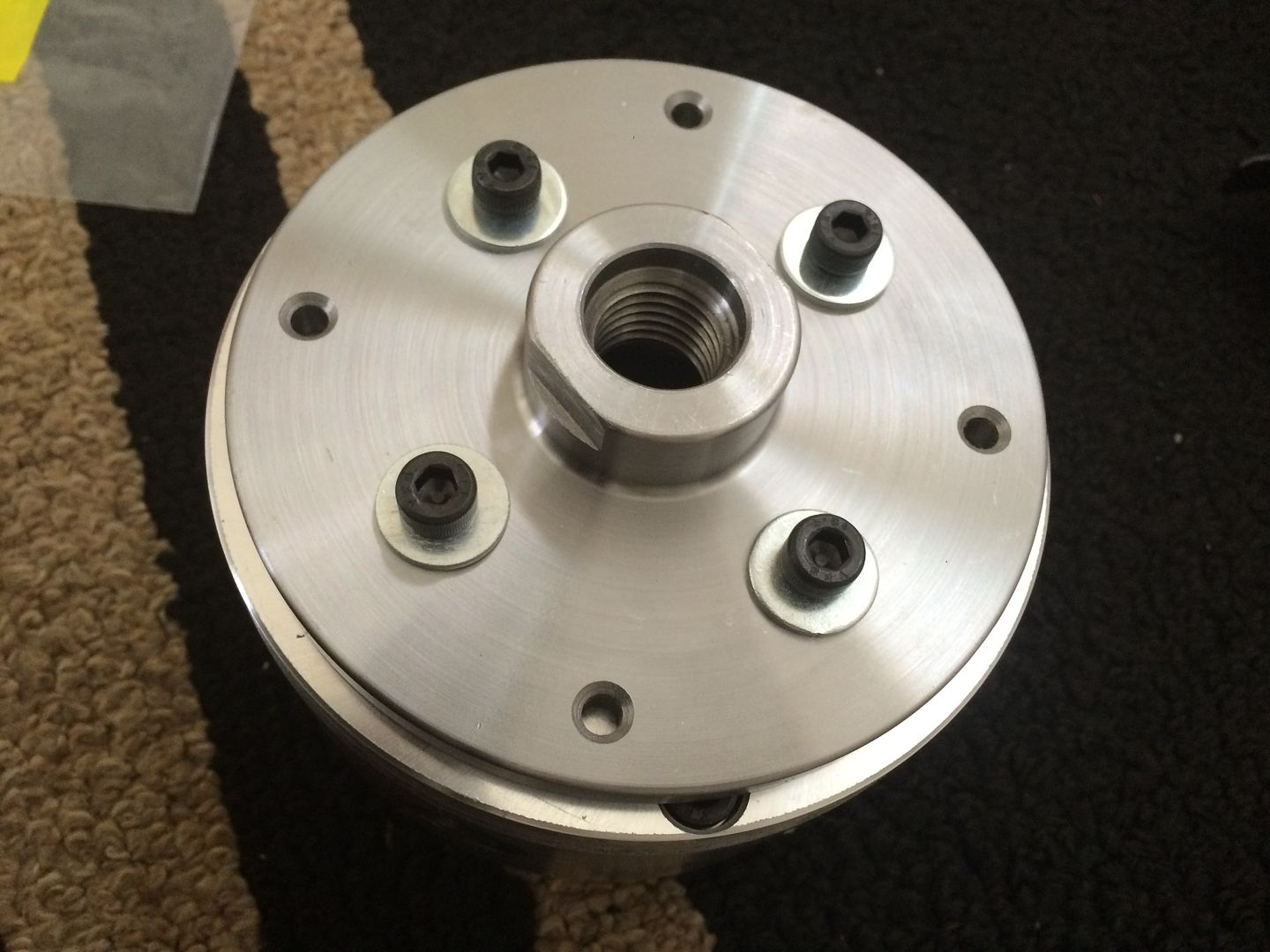
ive had one of the two copper pieces for a while... i sent my friend some copper to make my threaded adapter... i picked up a 6" chuck, 3 jaw self centering... though I wish I would have found a slimmer one.. this one will work perfect... the chuck would not work with the backing plate i have.. .instead of getting a new one, and so that i could keep the 1" shaft setup, I programmed a simple adapter plate... and had my machinist cut it on his cnc.... as i have done for a ton of projects...
here is where i am at right now, currently looking for a motor and controller, for a decent deal... still trying to keep this budget friendly... but may program something for the laser to cut, so that i can puzzle piece a nice tilting setup/enclosure together... and this way anyone who likes how this comes put, for the budget, can have a head start too...
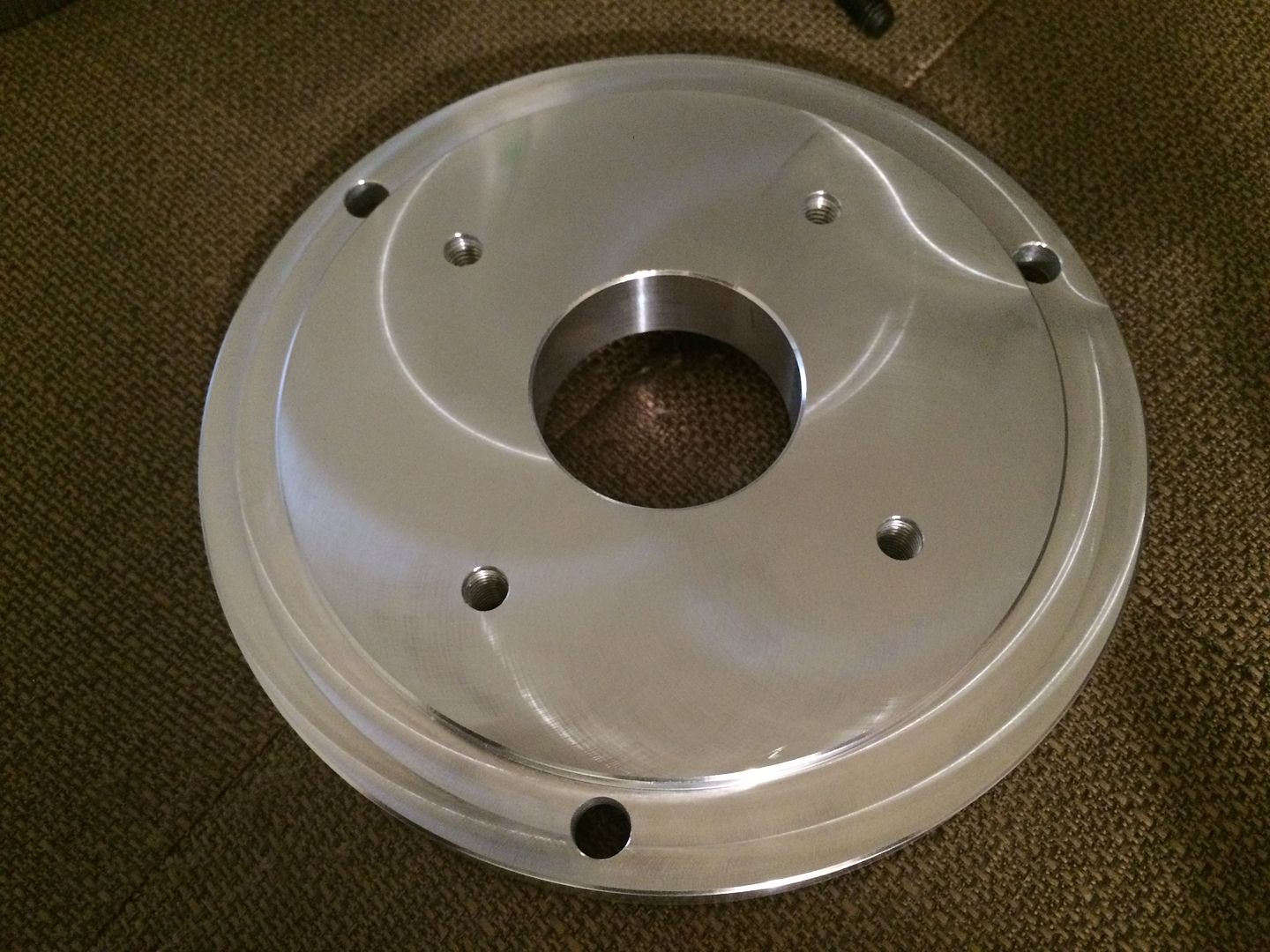
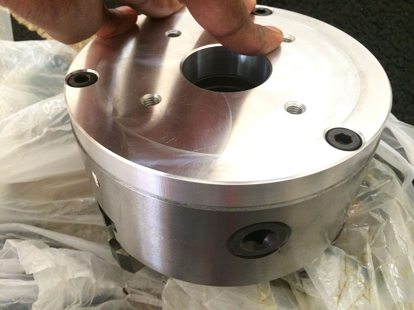
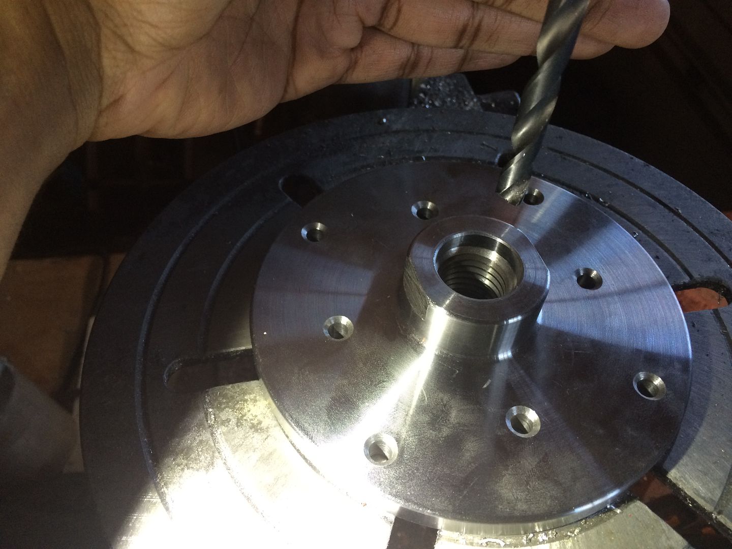
i programmed it where it would fit very tightly inside the recessed portion of the chuck...
and added threaded holes to bolt the original backing plate on...
back to some of these projects...
ive had one of the two copper pieces for a while... i sent my friend some copper to make my threaded adapter... i picked up a 6" chuck, 3 jaw self centering... though I wish I would have found a slimmer one.. this one will work perfect... the chuck would not work with the backing plate i have.. .instead of getting a new one, and so that i could keep the 1" shaft setup, I programmed a simple adapter plate... and had my machinist cut it on his cnc.... as i have done for a ton of projects...
here is where i am at right now, currently looking for a motor and controller, for a decent deal... still trying to keep this budget friendly... but may program something for the laser to cut, so that i can puzzle piece a nice tilting setup/enclosure together... and this way anyone who likes how this comes put, for the budget, can have a head start too...
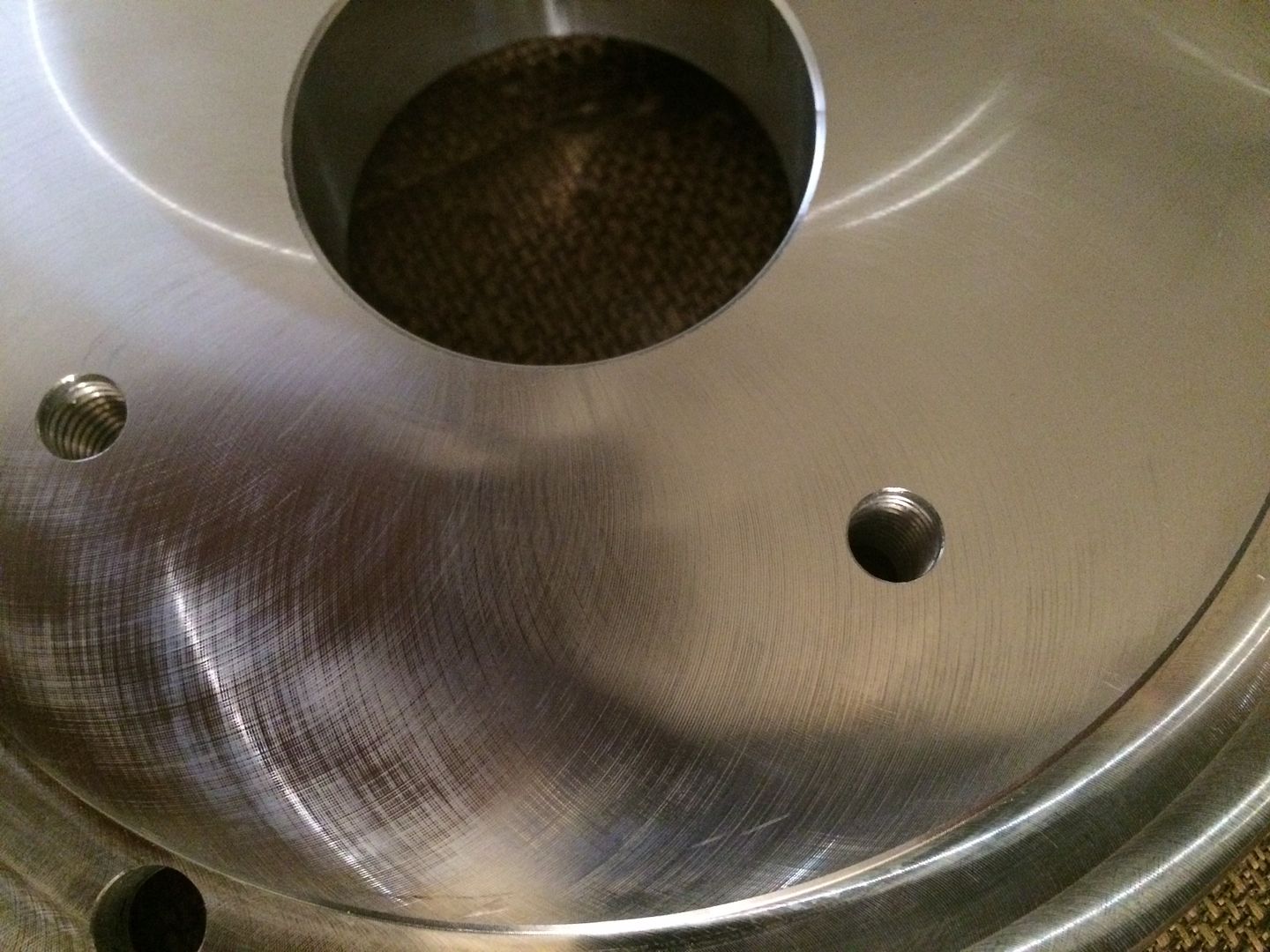
i programmed it where it would fit very tightly inside the recessed portion of the chuck...
and added threaded holes to bolt the original backing plate on...
LS Customs
- LS Customs
-
Ace
-
Posts:
-
Joined:Tue Feb 23, 2016 11:56 pm
LS Customs
- LS Customs
-
Ace
-
Posts:
-
Joined:Tue Feb 23, 2016 11:56 pm
LS Customs
- LS Customs
-
Ace
-
Posts:
-
Joined:Tue Feb 23, 2016 11:56 pm
LS Customs
- LS Customs
-
Ace
-
Posts:
-
Joined:Tue Feb 23, 2016 11:56 pm
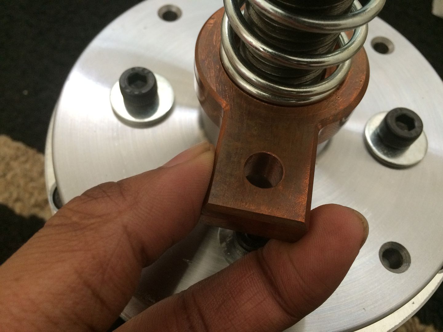
my other copper part screws into the bottom of the plate and the one in the pic, attaches to the ground cable... the spring will keep tension on the two pieces, as it spins, or if there is somehow some wear throughout the years? the tension is adjustable, depending on how tight the nut is tightened against the ground lug... hope that makes sense...
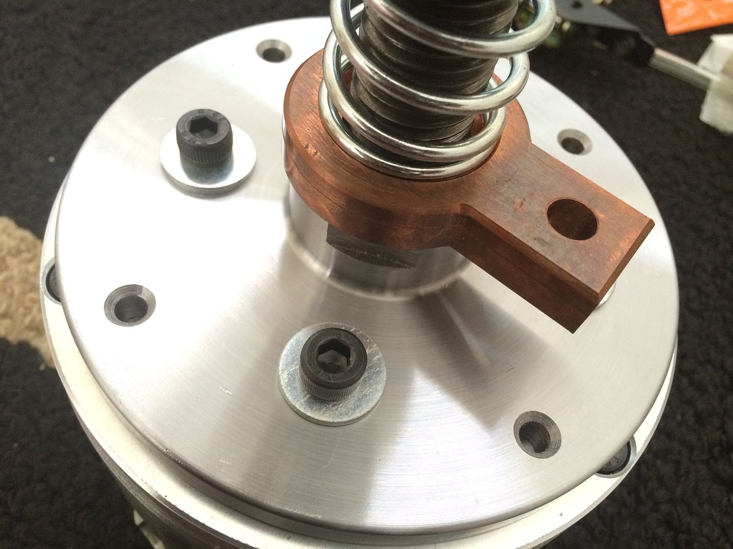
the spring sits in the pocket on the copper lug... not that it needed it, but that i wanted it to sit nicely and purposefully
LS Customs
- LS Customs
-
Ace
-
Posts:
-
Joined:Tue Feb 23, 2016 11:56 pm
waiting on this part to be machined, when my friend can take care of it for me... it is prob not necessary, and the setup may ground nicely as is, but I wanted to make sure, and i figured, if i make one piece thread right into the plate, it would be an awesome ground, and then the two pieces of copper can rub against each other, and not the steel on copper...
i am currently researching and looking for a nice motor and controller, if possible, budget friendly. but this setup will be way less overall, then what I intended to buy in the first place... since i am not a shop, i try not to spend so much, on something that may not be used often enough to pay for itself... i really wanted an mbc positioner... but this should do all that i want it to do and for a very nice price... hopefully
i am currently researching and looking for a nice motor and controller, if possible, budget friendly. but this setup will be way less overall, then what I intended to buy in the first place... since i am not a shop, i try not to spend so much, on something that may not be used often enough to pay for itself... i really wanted an mbc positioner... but this should do all that i want it to do and for a very nice price... hopefully
LS Customs
- LS Customs
-
Ace
-
Posts:
-
Joined:Tue Feb 23, 2016 11:56 pm
i also need to make something to hold the tig torch, if i need to... and a steady rest for me to be in a comfortable, consistent position, while not using the holder (which will be most of the time, as i can use it when not using the positioner too)... welding for me has been a very key part in my fight against cancer... it has given me something to either do or think about, when i couldnt do much else... i learned very quick to get into as comfortable position as possible, which is why i started this project...

- MosquitoMoto
-
Weldmonger
-
Posts:
-
Joined:Sat Aug 01, 2015 8:38 am
-
Location:The Land Down Under
You are doing great work and the pics are great, too.
Just wanted to wish you all the best with your recovery - I hope that you manage to find all the energy and focus that you need to make it back into great shape.
I suffered a brain injury a few years ago and needed emergency neurosurgery, after which I had two strokes and a long stay in ICU, then lots of rehabilitation and learning to do 'everything' again. My motorcycles and workshop played a huge part in me starting to feel good again and really get better. I hope that welding will do the same for you and I really hope that the worst is behind you and every day is better from here on.
Kym
LS Customs
- LS Customs
-
Ace
-
Posts:
-
Joined:Tue Feb 23, 2016 11:56 pm
thank you very very much... we r in it to win it... i sold few my harley and a few other toys, when i found out i had cancer... will have to grab another in a while... first time i have been without some sort of motorcycle, since 16...MosquitoMoto wrote:You are doing great work and the pics are great, too.
Just wanted to wish you all the best with your recovery - I hope that you manage to find all the energy and focus that you need to make it back into great shape.
I suffered a brain injury a few years ago and needed emergency neurosurgery, after which I had two strokes and a long stay in ICU, then lots of rehabilitation and learning to do 'everything' again. My motorcycles and workshop played a huge part in me starting to feel good again and really get better. I hope that welding will do the same for you and I really hope that the worst is behind you and every day is better from here on.
Kym
LS Customs
- LS Customs
-
Ace
-
Posts:
-
Joined:Tue Feb 23, 2016 11:56 pm
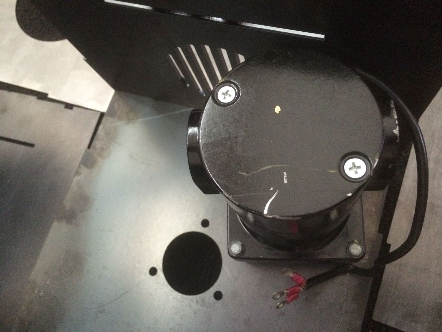
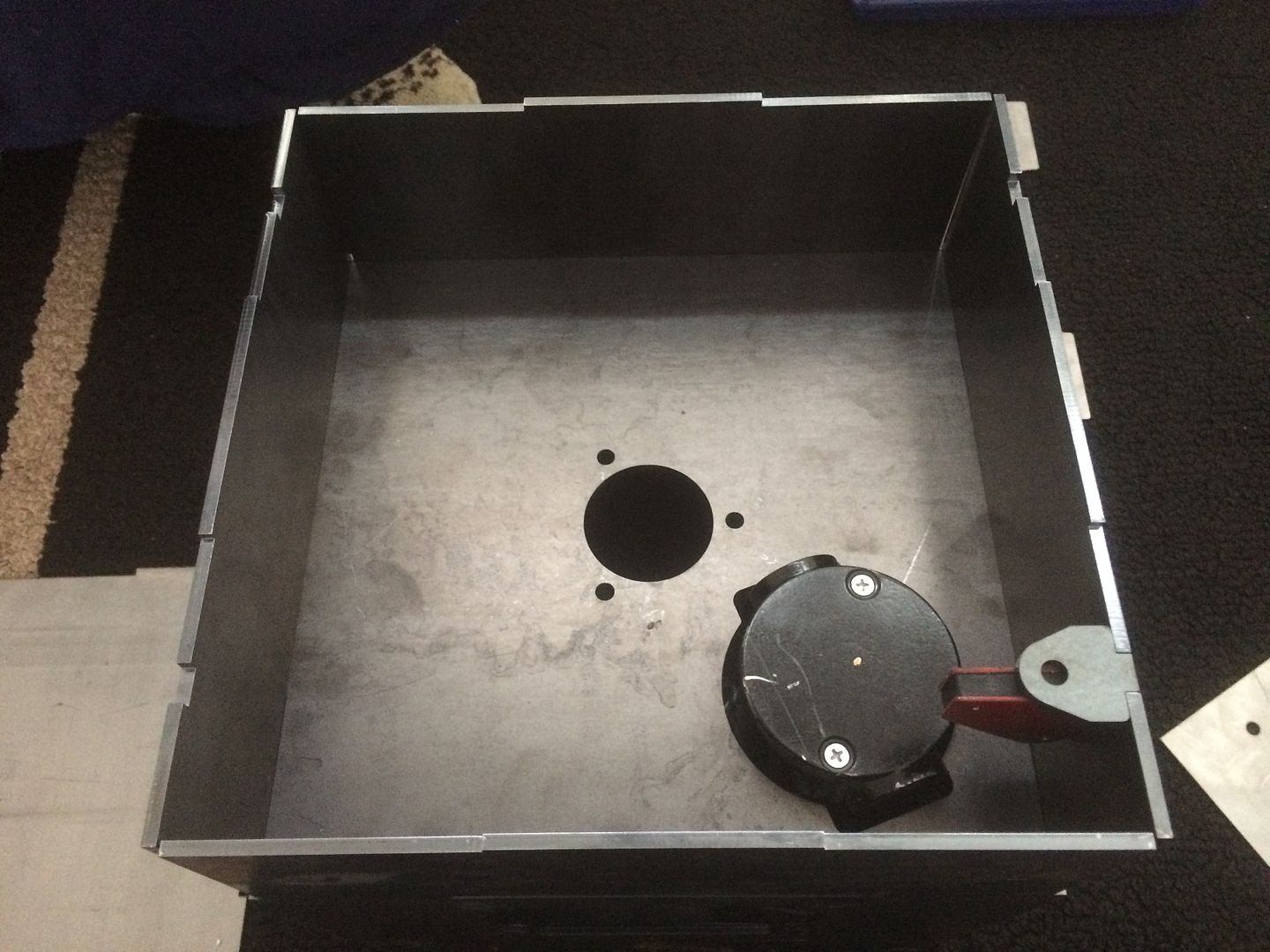
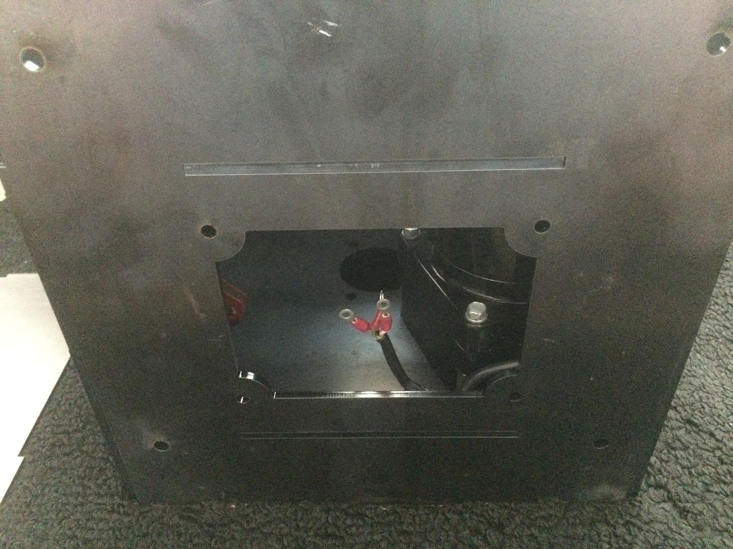
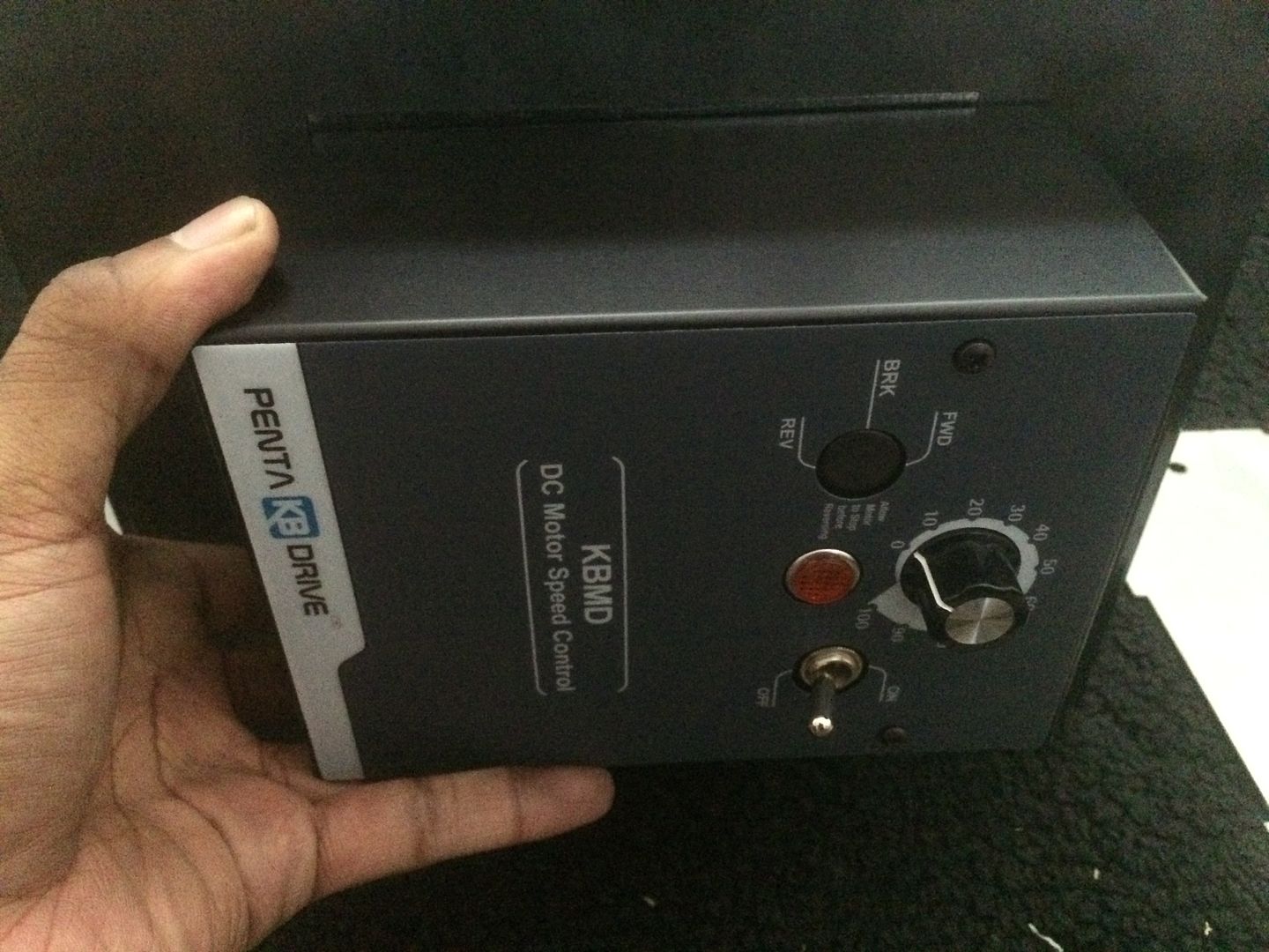
found a motor, i hope will work (used)... didnt want to risk getting the controller or parts used, so i bought those new... could have saved quite a bit doing it slightly different, but i hope to have somethng that lasts a long long time, when done... i figured if i had bad luck with the used motor, i could always get another, but i wanted the electronics to be sound... using the KBMD Controller...
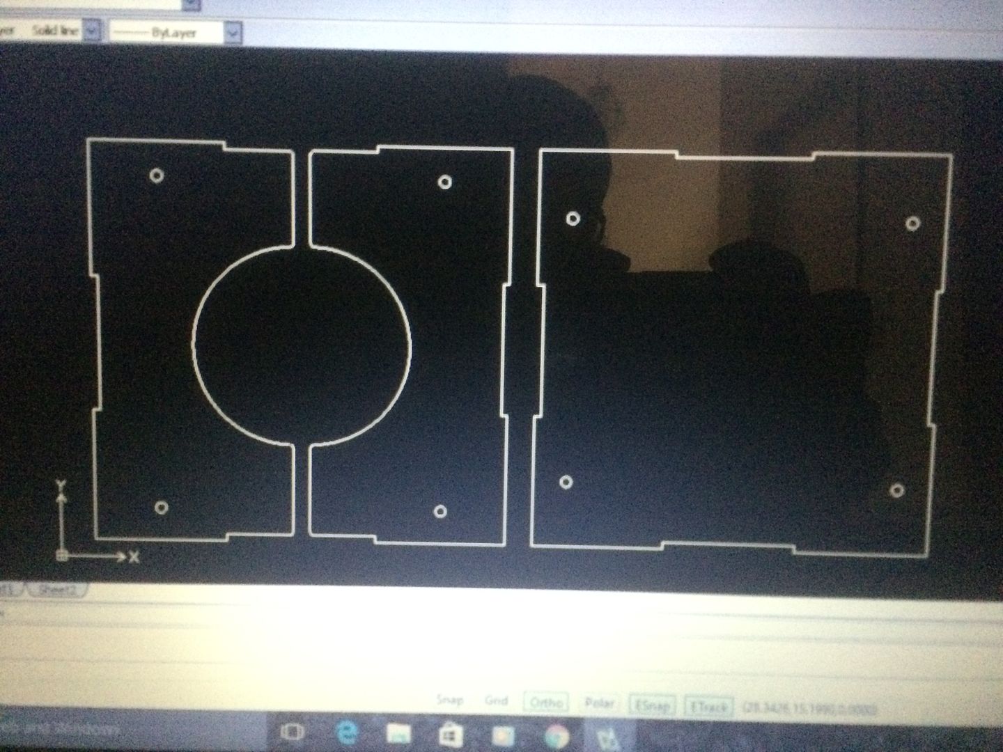
also did a quick dxf program for laser... using some dimensions i got off line for the motor... it will sit in the enclosure upside down so to speak... i hope i have the measurements right as Bodine apparently doesnt offer the motor any more... (BODINE 32ABEPM-W4 DC GEARMOTOR)
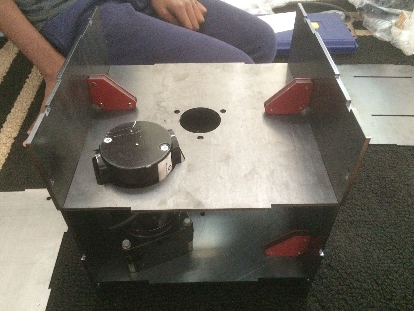
i hope 1/8" thick steel will be strong enough, as it is "boxed" and will be braced in the inside... I would make one or two panels bolt on.. but this would fit together like a puzzle to make things a bit easier... shouldnt cost much to laser cut, if i have to, ill have to get down to my friends shop and operate the laser myself (learned to run it a while ago)
going to add a few logos, of some sort (just so it doesnt look as plain) and fine tune it once i get the parts in...
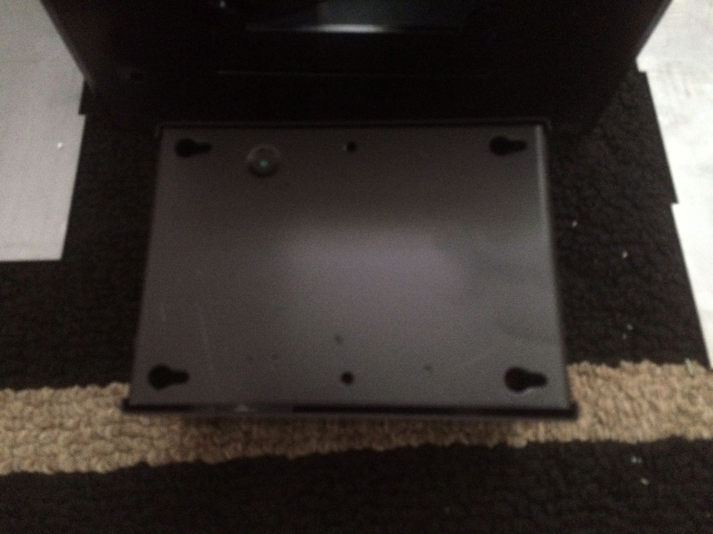
also saw where someone else had used an engine stand to help make his a tilting setup... i am adding some mounting holes on one side to be able to bolt on and off a stand (which i already have anyway)... can also make a bench top stand work with it also.. but an engine stand is easy enough to adapt, by adding four holes
also did a quick dxf program for laser... using some dimensions i got off line for the motor... it will sit in the enclosure upside down so to speak... i hope i have the measurements right as Bodine apparently doesnt offer the motor any more... (BODINE 32ABEPM-W4 DC GEARMOTOR)
i hope 1/8" thick steel will be strong enough, as it is "boxed" and will be braced in the inside... I would make one or two panels bolt on.. but this would fit together like a puzzle to make things a bit easier... shouldnt cost much to laser cut, if i have to, ill have to get down to my friends shop and operate the laser myself (learned to run it a while ago)
going to add a few logos, of some sort (just so it doesnt look as plain) and fine tune it once i get the parts in...
also saw where someone else had used an engine stand to help make his a tilting setup... i am adding some mounting holes on one side to be able to bolt on and off a stand (which i already have anyway)... can also make a bench top stand work with it also.. but an engine stand is easy enough to adapt, by adding four holes
LS Customs
- LS Customs
-
Ace
-
Posts:
-
Joined:Tue Feb 23, 2016 11:56 pm
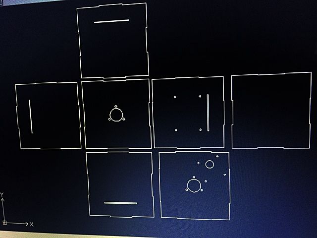
ended up with this as a final program...
these are 3/16" thick... most will be welded, but one side will bolt on, as i need to access the motor, etc, if need be
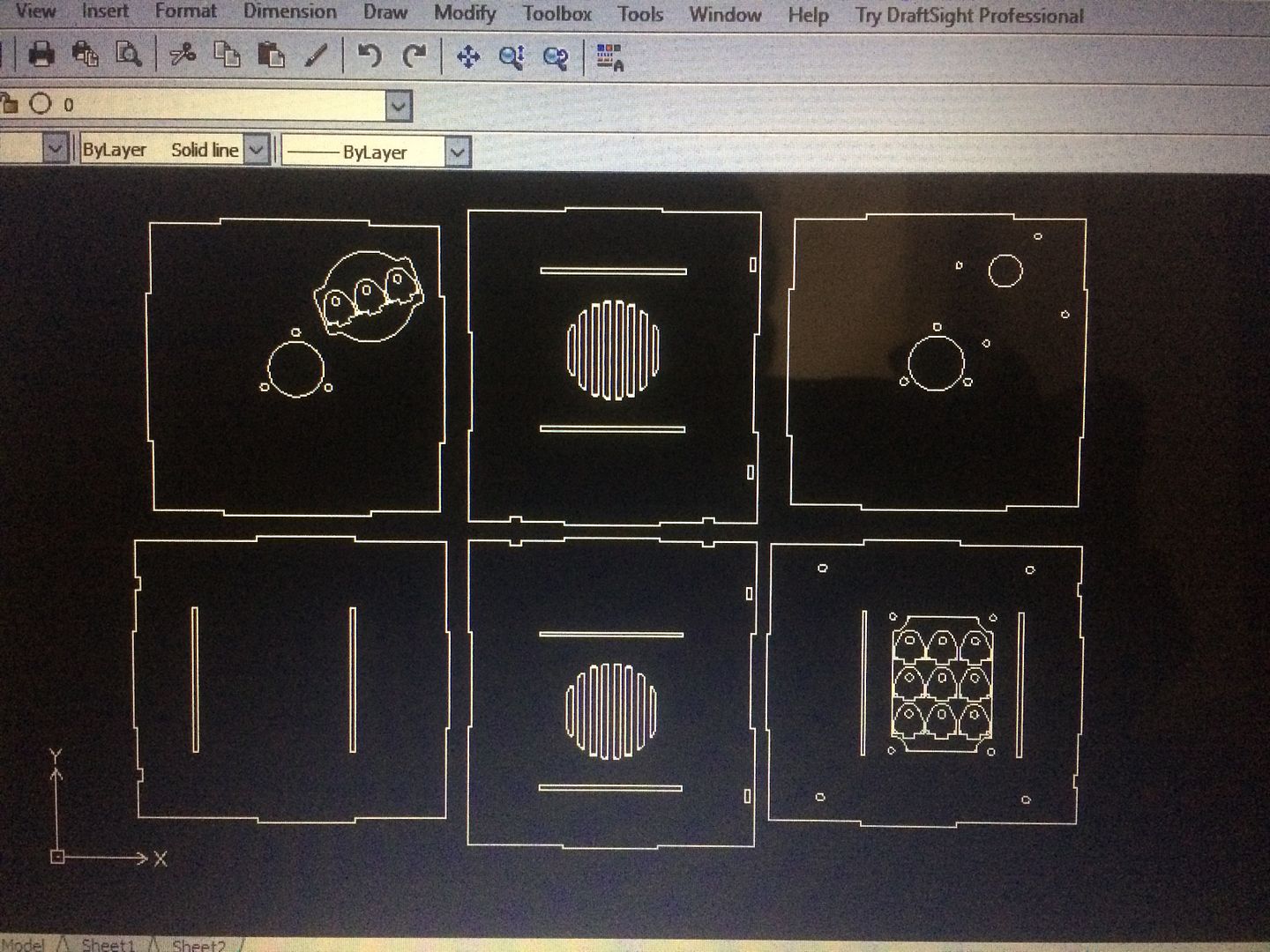
these are 1/8" thick and are covers...
these are 3/16" thick... most will be welded, but one side will bolt on, as i need to access the motor, etc, if need be
these are 1/8" thick and are covers...
LS Customs
- LS Customs
-
Ace
-
Posts:
-
Joined:Tue Feb 23, 2016 11:56 pm
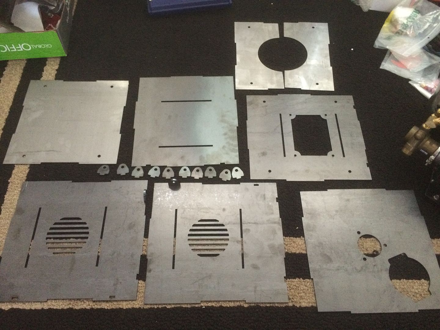
the tabs, will have nuts welded on them...
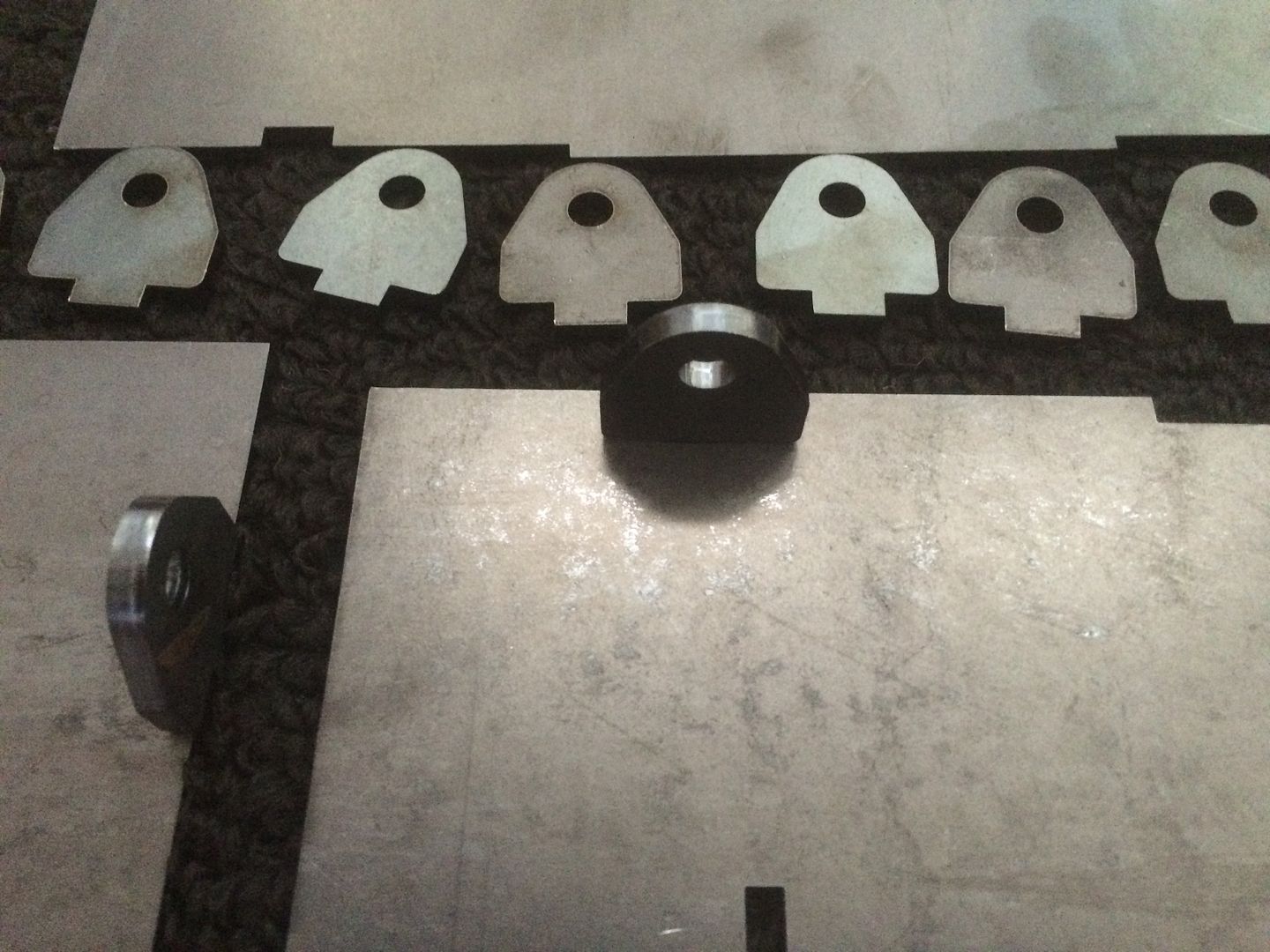
misc slots for the tabs
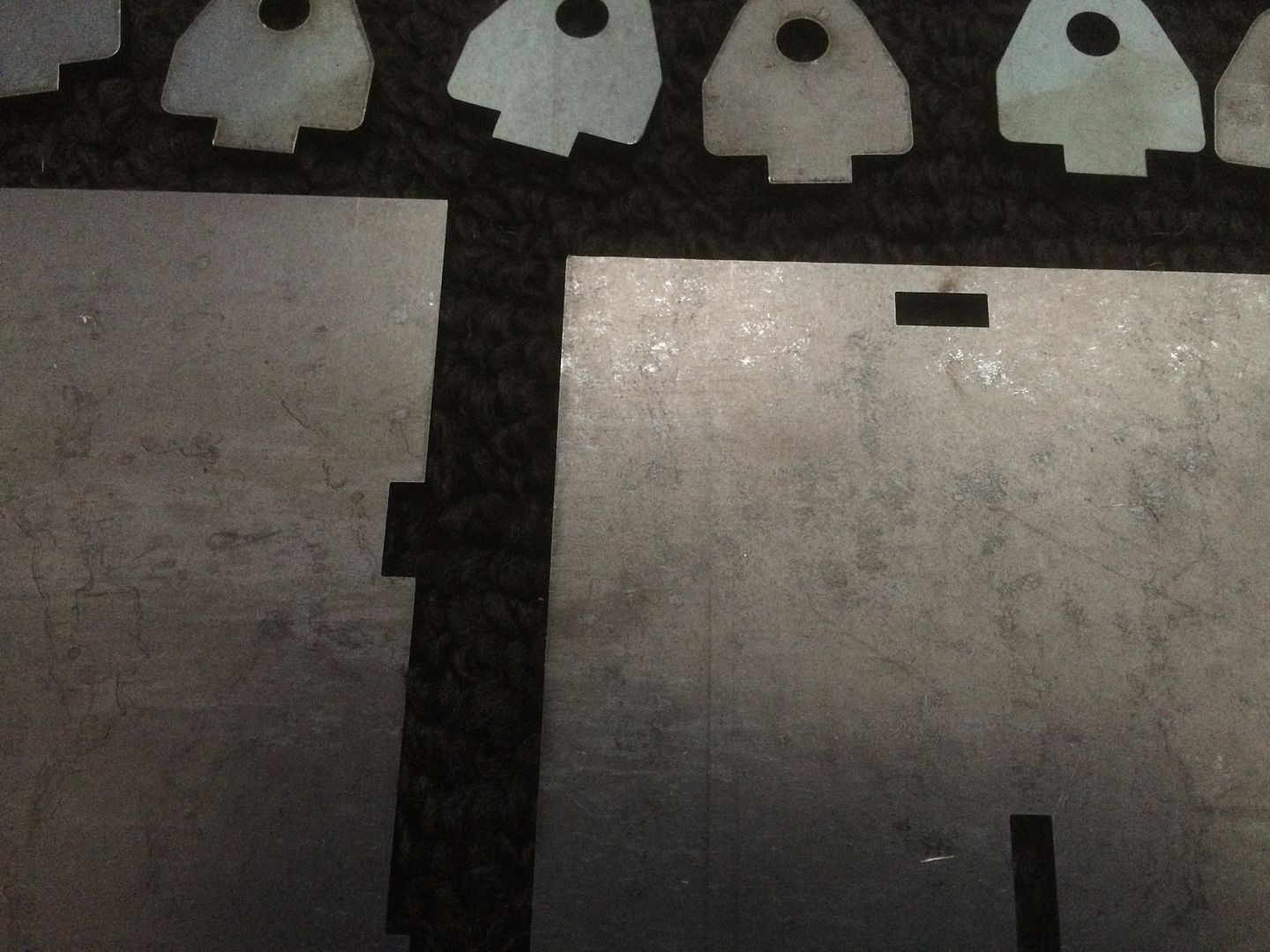
just helps as sort of a self jig
LS Customs
- LS Customs
-
Ace
-
Posts:
-
Joined:Tue Feb 23, 2016 11:56 pm
LS Customs
- LS Customs
-
Ace
-
Posts:
-
Joined:Tue Feb 23, 2016 11:56 pm
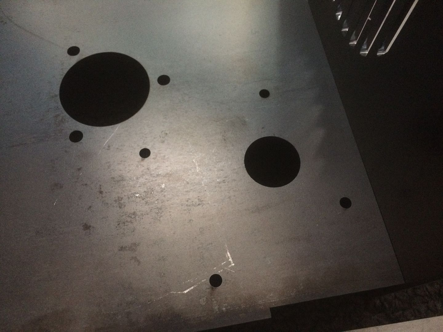
also programmed in the bolt hole pattern for the controller and that fit correctly also...
i do have the proper switch, fuse etc, for the controller also
Last edited by LS Customs on Tue Jun 07, 2016 12:11 am, edited 1 time in total.
Return to “Welding Projects - Welding project Ideas - Welding project plans”
Jump to
- Introductions & How to Use the Forum
- ↳ Welcome!
- ↳ Member Introductions
- ↳ How to Use the Forum
- ↳ Moderator Applications
- Welding Discussion
- ↳ Metal Cutting
- ↳ Tig Welding - Tig Welding Aluminum - Tig Welding Techniques - Aluminum Tig Welding
- ↳ Mig and Flux Core - gas metal arc welding & flux cored arc welding
- ↳ Stick Welding/Arc Welding - Shielded Metal Arc Welding
- ↳ Welding Forum General Shop Talk
- ↳ Welding Certification - Stick/Arc Welding, Tig Welding, Mig Welding Certification tests - Welding Tests of all kinds
- ↳ Welding Projects - Welding project Ideas - Welding project plans
- ↳ Product Reviews
- ↳ Fuel Gas Heating
- Welding Tips & Tricks
- ↳ Video Discussion
- ↳ Wish List
- Announcements & Feedback
- ↳ Forum News
- ↳ Suggestions, Feedback and Support
- Welding Marketplace
- ↳ Welding Jobs - Industrial Welding Jobs - Pipe Welding Jobs - Tig Welding Jobs
- ↳ Classifieds - Buy, Sell, Trade Used Welding Equipment
- Welding Resources
- ↳ Tradeshows, Seminars and Events
- ↳ The Welding Library
- ↳ Education Opportunities