Tig welding tips, questions, equipment, applications, instructions, techniques, tig welding machines, troubleshooting tig welding process
- jumpinjackflash
-
Guide

-
Posts:
-
Joined:Sun Feb 02, 2014 6:14 pm
-
Location:Near Mt Airy
This is out of my FAA repair manuals.....question is I feel like this suggested 1/8" gap is better suited for gas welding. The tube that is going to be replaced is all .035" wall and 3/8 , 1/2 OD. If I were planning to TIG all these splices as per the manual without that huge gap do you think it would be weak? Smaller gap? No gap has my reasoning...but always check with more knowledgeable than myself. I think trying to get 3 surfaces to wet out might be tough without cooking the tubes 
- Attachments
-
- Copied from AC 43.13 1-b acceptable methods aircraft inspection/repair
- 002.jpg (43.09 KiB) Viewed 1960 times
Building an airplane is at times somewhat like a divorce.....with the exception that she doesn't leave
J.J. Flash
J.J. Flash
Normally thin wall tube like this does not need a 1/8" gap, but your drawing shows an inner sleeve tube. In this case the 1/8" gap is there to ensure both ends of the tube and inner sleeve are all fused together.
Flat out like a lizard drinkin'
That's how I interrupt the print as well...Coldman wrote:Normally thin wall tube like this does not need a 1/8" gap, but your drawing shows an inner sleeve tube. In this case the 1/8" gap is there to ensure both ends of the tube and inner sleeve are all fused together.
I weld stainless, stainless and more stainless...Food Industry, sanitary process piping, vessels, whatever is needed, I like to make stuff.
ASME IX, AWS 17.1, D1.1
Instagram #RNHFAB
ASME IX, AWS 17.1, D1.1
Instagram #RNHFAB
I have zero aviation experience so it is interesting to me to see this joint design. Whoever designed this joint definitely did not want it to come apart or be the weak spot in the frame. The joint is reinforced by the inner tube, the sway taken out of it by the rosette welds and the joint is at 30* to disperse stresses on the joint. Beautiful.
If you are welding up an aviation frame I would not deviate from this design in any way. The risk is there.
Someone else uses inner tube joint design on boat rails. Was it Tam? Even if you don't need extra reinforcement it is a fast and easy way to align a butt joint without clamping and marking tube surface.
Flat out like a lizard drinkin'
- jumpinjackflash
-
Guide
-
Posts:
-
Joined:Sun Feb 02, 2014 6:14 pm
-
Location:Near Mt Airy
I get that they all get fused together...but do you think I could close the gap a tiny bit? I guess I need to make some practice pieces and just see what happens...then cut them and see what got fused. I'll get pix up when I get the tests done...thin and small pieces.
Thanks guys
Thanks guys
Building an airplane is at times somewhat like a divorce.....with the exception that she doesn't leave
J.J. Flash
J.J. Flash

I don't remember what thread it was, but there was one not too long ago about TIG on air frame construction.
I seem to remember that there was some concern that the tighter HAZ from TIG was not as structurally sound as the much softer/wider HAZ from O/A welded joints in the same structures.
Take that with as many grains of salt as you care to, though. I work in aviation, but am not an A&P, nor a structural or process engineer.
-Josh
Greasy fingered tinkerer.
Greasy fingered tinkerer.
- Otto Nobedder
-
Weldmonger

-
Posts:
-
Joined:Thu Jan 06, 2011 11:40 pm
-
Location:Near New Orleans
No! Don't close the gap. Weld it exactly as described. Treat it like a WPS. You have no leg to stand on, if your joint fails and you deviated from a recommended practice.jumpinjackflash wrote:I get that they all get fused together...but do you think I could close the gap a tiny bit? I guess I need to make some practice pieces and just see what happens...then cut them and see what got fused. I'll get pix up when I get the tests done...thin and small pieces.
Thanks guys
Steve S


^^^^^
This
Also you need to think about the reasoning behind this style of repair. Why is it done like this? Especially on airframes there's more often than not a very good reason why things are done in a certain way. (aka. to stop gravity winning )
)
What it looks to me that they are trying to achieve is that the repair itself returns the strenght in the construction becasue the inner tube that's slid into the main pipes is becoming the new structural member of the joint and not because they are re-welding the original tubes together.
The rosette welds and the main (lap)welds around the tube are to provide the interlock between the original tube and the repair tube that's put inside.
The gap is there because the welds are not threre to join the original pipes together but to connect the inner to the outer pipes and the inner pipe provides the structural integrity of the joint itself.
The inner tube and the gap between the main pipes are probably the crucial parts of this repair and must not be altered from the requirments on the drawing.
BYe, Arno.
This
Also you need to think about the reasoning behind this style of repair. Why is it done like this? Especially on airframes there's more often than not a very good reason why things are done in a certain way. (aka. to stop gravity winning
What it looks to me that they are trying to achieve is that the repair itself returns the strenght in the construction becasue the inner tube that's slid into the main pipes is becoming the new structural member of the joint and not because they are re-welding the original tubes together.
The rosette welds and the main (lap)welds around the tube are to provide the interlock between the original tube and the repair tube that's put inside.
The gap is there because the welds are not threre to join the original pipes together but to connect the inner to the outer pipes and the inner pipe provides the structural integrity of the joint itself.
The inner tube and the gap between the main pipes are probably the crucial parts of this repair and must not be altered from the requirments on the drawing.
BYe, Arno.

Consider this. If you deviate away from the approved data in AC 43.13, you'll have to get a field approval from the FSDO, who will probably want to know why the 43.13 data won't work for your repair. And then the field approval, in this day and age of litigation, will probably take thousands of dollars and months or years to get data approval.
- jumpinjackflash
-
Guide
-
Posts:
-
Joined:Sun Feb 02, 2014 6:14 pm
-
Location:Near Mt Airy
Tubes marked for cutting....proceeding with repair as stated in manual. My A&P with I/A auth. said for me to not deviate. Proven, time tested theory from the "30s to now. I simply said OK .
Building an airplane is at times somewhat like a divorce.....with the exception that she doesn't leave
J.J. Flash
J.J. Flash
- Otto Nobedder
-
Weldmonger
-
Posts:
-
Joined:Thu Jan 06, 2011 11:40 pm
-
Location:Near New Orleans
" 'cause that's the way we've always done it" is sometimes good enough, when the rules back it up. That's why I said "no, don't deviate."jumpinjackflash wrote:Tubes marked for cutting....proceeding with repair as stated in manual. My A&P with I/A auth. said for me to not deviate. Proven, time tested theory from the "30s to now. I simply said OK .
Steve S
- jumpinjackflash
-
Guide
-
Posts:
-
Joined:Sun Feb 02, 2014 6:14 pm
-
Location:Near Mt Airy
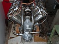
OK Made all of the pieces for the repair job. I welded up a couple test parts just like the joints to be repaired. I thought I would blow off the end of the tube where it feathers down to nothing on the ends...and it did to some extent. The welds are not as pretty as I would like...but function is important and not burning up the tube. I think the test came out OK. The inner sleeve wound up being .042" wall inside the .035" wall new replacement tubing. Gap was right at .123" wide after tacking up. Had to keep somewhat of a big plume near the feathered edges of the tubes to try and get it with one pass. Using .045" filler helped a lot, but probably has a lot of push through. No undercut and all wetted out decent. I did let it cool between each 1/4 of the weld, but didn't get enough filler in spots near the tube ends where it melted away. You think this test is good enough results to go ahead with the repair?
- Attachments
-
- 0711152040.jpg (20.91 KiB) Viewed 807 times
-
- 0711152010.jpg (19.03 KiB) Viewed 808 times
Building an airplane is at times somewhat like a divorce.....with the exception that she doesn't leave
J.J. Flash
J.J. Flash
Return to “Tig Welding - Tig Welding Aluminum - Tig Welding Techniques - Aluminum Tig Welding”
Jump to
- Introductions & How to Use the Forum
- ↳ Welcome!
- ↳ Member Introductions
- ↳ How to Use the Forum
- ↳ Moderator Applications
- Welding Discussion
- ↳ Metal Cutting
- ↳ Tig Welding - Tig Welding Aluminum - Tig Welding Techniques - Aluminum Tig Welding
- ↳ Mig and Flux Core - gas metal arc welding & flux cored arc welding
- ↳ Stick Welding/Arc Welding - Shielded Metal Arc Welding
- ↳ Welding Forum General Shop Talk
- ↳ Welding Certification - Stick/Arc Welding, Tig Welding, Mig Welding Certification tests - Welding Tests of all kinds
- ↳ Welding Projects - Welding project Ideas - Welding project plans
- ↳ Product Reviews
- ↳ Fuel Gas Heating
- Welding Tips & Tricks
- ↳ Video Discussion
- ↳ Wish List
- Announcements & Feedback
- ↳ Forum News
- ↳ Suggestions, Feedback and Support
- Welding Marketplace
- ↳ Welding Jobs - Industrial Welding Jobs - Pipe Welding Jobs - Tig Welding Jobs
- ↳ Classifieds - Buy, Sell, Trade Used Welding Equipment
- Welding Resources
- ↳ Tradeshows, Seminars and Events
- ↳ The Welding Library
- ↳ Education Opportunities