Pedal Control Relative to Amp Input + Deep Dive Into the Dark Side of Heat Input and Thermal Conductivity
The idea here isn't necessarily an idea, it's more of a theory of theories in my way of notation for sharing. The initial focus is on how the Amperage range is affected by the travel of pedal. One day I might include the 22k vs. 47k Ohm differences... Later it goes into the physics and sciences relative to welding, as I try to theorize how it all "clicks" together. Read on if you dare and call me crazy if you'd like!
My Basic Everlast 22k Ohm pedal has 10 clicks for full pedal travel. The total travel is 25 degrees. The first half of the pedal is easy to push but after 50% push the tension in the spring is significantly increasing giving a slightly harder press and stronger return i.e. less control.
To puddle my metal I have to have Y number of Amps at X work piece temperature in N seconds. These numbers are determined by what you know and how fast you can go.
By taking the total of 10 clicks and using only half which is 5 for my easy ride, and using the upper half of the 6-10 for starting the puddle, I can then do some tests and math to find a pretty good set of values to use with the pedal and it can also help me figure out just how many Amps I've been using.
For my aluminum I was running 150 Amps at the dial and with a part at 110-110F I was able to use the 10 clicks to start my puddle, then feathering around 6-8 for about the first 1/2 in, and then towards 2-5 for the rest and I'd generally get a decent bead that was shiny with a good travel speed I am comfortable with.
With 150A as the high and 0 as the low with the 10 points of travel in the pedal we can infer the increments are 15A per click so I'm starting out with 150A and tapering off between 90-120A as I begin travel and pulse the pedal, then continue after that 1/2in at about 30-75A.
Without clicks, we can infer every degree equals 6 Amps since 150A / 25 degrees = 6A per Degree.
If it was 200 Amps I'd have 20 Amps per click or 8 Amps per degree.
You can take this information to make some affirmations about where you're at or where you need to go. There is more to it but I think this is good for those ball park figures.
Now I'm about to get deep in an area I'm researching but don't fully understand.... This is not ME telling YOU how it is, these are my notes regarding all my research thus far. I'm wondering if I'm missing something or if this is what I should be thinking about as I delve into the science/physics of welding.
So on to the theoretical notes:
I would imagine we should take this further and consider the solidus and liquidus states of the materials. I've listed some examples below:
Aluminum
Solidus 582 °C 1080 °F AA; Typical
Liquidus 652 °C 1205 °F AA; Typical
11% difference between solidus and liquidus
125F Degrees difference between solidus and liquidus
plain carbon steel
Soliuds 1,130 °C (2,070 °F)
Liquidus 1,492 °C (2,718 °F)
24% difference between solidus and liquidus
648F Degrees difference between solidus and liquidus
Stainless steel 304L
Solidus 1400 °C 2550 °F
Liquidus 1450 °C 2640 °F
4% difference between solidus and liquidus
90F Degrees difference between solidus and liquidus
What this would tell me is that between my lowest and highest points (once things are going) of my pedal press should be relative to the difference between solidus and liquidus so if the difference is 10% then the difference between the high and low pedal press should be around 10% of the necessary Amps for the metal to remain between solidus and liquidus.
The question that would drive your range is whether you'd want to keep in the liquidus state or go to or below solidus to freeze before your next pulse since this would set your range. I'd imagine the solidus/liquidus difference percentage should be equal or be close to the difference percentage you've come up with for your pedal travel vs. Amps needed to melt relative to how much melt you want.
You might be able to find this range easier by finding what the highest Amp you can run and not melt the metal and the lowest Amp you can run to begin melting the metal. Sound easy enough but this is where thermal conductivity ensures you will "never" have a constant Amp value.
Let's really fall at terminal velocity down the rabbit hole....
Now I do not understand a direct way to write out how thermal conductivity plays it's part but Jody did give the Heat Input equation that helps determine some of this in one of his videos, just can't remember which one... I'm posting all these thoughts and the rest of this information to see if perhaps some science expert can make some of this simpler, tell me I'm completely wrong, and/or tell me I'm missing something...It's also for me to reference as time goes on to see if I can't make more sense of it and this wasn't easily put together.
Heat Input equation:
Heat Input(KiliJoules per mm or inch (kJ/mm or kJ/in)) = (Voltage X Amperage X Time) / (DistanceTraveled in/mm X 1000)
1 Joule = 4.186 Calories
1 Joule = .000239 Kilocalorie
1 Joule = .0239 Calorie
1 Joule = 0.000526565076466 Celcius Heat Units
1 Calorie = 4.1868 Watts Per Second
1 Amp = 12 Watts / 12 Volts
1 Amp = 9 Watts / 9 Volts
1 Amp = 9999 Watts / 9999 Volts
Watts = Amps * Volts
1000 Watts = 100 Amps * 9 Volts
1 Calorie is required to increase the temperature of one gram of water by 1C.
1 Celcius heat unit is required to raise the temperature of 1Lbs of water by 1C.
TIG perfect arc is ~9 Volts
Thermal Conductivity of Materials
http://www.engineeringtoolbox.com/therm ... d_429.html
- k - W/(m K)
Material 25C 125C 225C
Aluminum 205 215 250
Carbon Steel 54 51 47
Stainless Steel 16 17 19
Water 0.58
Conductive Heat Transfer through an Aluminum Pot Wall with thickness 2 mm - temperature difference 80C
Thermal conductivity for aluminum is 215 W/(m K) (from the table above). Conductive heat transfer per unit area can be calculated as
q / A = (215 W/(m K)) (80C) / (2 10^3 m)
= 8600000 (W/m^2)
= 8600 (kW/m^2)
Conductive Heat Transfer through a Stainless Steel Pot Wall with thickness 2 mm - temperature difference 80C
Thermal conductivity for stainless steel is 17 W/(m K) (from the table above). Conductive heat transfer per unit area can be calculated as
q / A = (17 W/(m K)) (80C) / (2 10^3 m)
= 680000 (W/m^2)
= 680 (kW/m^2)
http://www.engineeringtoolbox.com/condu ... d_428.html
Conduction as heat transfer takes place if there is a temperature gradient in a solid or stationary fluid medium.
With conduction energy transfers from more energetic to less energetic molecules when neighboring molecules collide. Heat flows in direction of decreasing temperatures since higher temperatures are assCiated with higher molecular energy.
Conductive heat transfer can be expressed with "Fourier's Law":
q = k A dT / s (1)
where
q = heat transfer (W, J/s, Btu/hr)
A = heat transfer area (m2, ft2)
k# = thermal conductivity of material (W/m K or W/m C, Btu/(hr F ft2/ft))
dT = temperature gradient - difference - in the material (K or C, F)
s# = material thickness (m, ft)
Example - Heat Transfer by Conduction
A plane wall is constructed of solid iron with thermal conductivity 70 W/mC. Thickness of the wall is 50 mm and surface length and width is 1 m by 1 m. The temperature is 150C on one side of the surface and 80C on the other.
The conductive heat transfer through the wall can be calculated
q = (70 W/m C) (1 m) (1 m) ((150C) - (80C)) / (0.05 m)
= 98000 (W)
= 98 (kW)
Heat Transfer through Plane Walls or Layers in Series
Heat conducted through several walls or layers in thermal contact can be expressed as
q = (T1 - Tn) / ((s1 / k1 A) + (s2 / k2 A) + ... + (sn / kn A)) (2)
where
T1 = temperature inside surface (K or C, F)
Tn = temperature outside surface (K or C, F)
Example - Heat Transfer through a Furnace Wall
A furnace wall of 1 m^2 consist of 1.2 cm thick stainless steel inner layer covered with 5 cm outside insulation layer of insulation board. The inside surface temperature of the steel is 800 K and the outside surface temperature of the insulation board is 350 K. The thermal conductivity of the stainless steel is 19 W/(m K) and the thermal conductivity of the insulation board is 0.7 W/(m K).
The conductive heat transport through the layered wall can be calculated as
q = ((800 K) - (350 K)) / (((0.012 m) / (19 W/(m K)) (1 m^2)) + ((0.05 m) / (0.7 W/(m K)) (1 m^2)))
= 6245 (W)
Thermal Conductivity Units
Btu/(h ft^2 oF/ft)
Btu/(h ft^2 oF/in)
Btu/(s ft^2 oF/ft)
MW/(m^2 K/m)
kW/(m^2 K/m)
W/(m^2 K/m)
W/(m^2 K/cm)
W/(cm^2 C/cm)
W/(in^2 oF/in)
kJ/(h m^2 K/m)
J/(s m^2 C/m)
kcal/(h m^2 C/m)
cal/(s cm^2 C/cm)
1 W/(m K) = 1 W/(m C) = 0.85984 kcal/(h m C) = 0.5779 Btu/(ft h F) = 0.048 Btu/(in h F)
A fairly complete list of metals and their thermal conductive properties:
http://www.engineeringtoolbox.com/therm ... d_858.html
Another site with a nifty nomograph calculator that explains heat input in great detail for various steels although it fCuses on stick/MIG. The principles should be the same:
http://www.arcraftplasma.com/welding/we ... errous.htm
For thermal conductivity which includes equations for geometry relative to heat convection:
http://www.roymech.co.uk/Related/Thermo ... nsfer.html
Lastly, here's a site that explains all of this in about the most simplest terms and puts a lot of the thoughts here together fairly well with useful equations and charts.
Lesson 1:
http://www.physicsclassroom.com/class/t ... t-Transfer
Lesson 2:
http://www.physicsclassroom.com/Class/t ... u18l2a.cfm
So to put everything together Thermal Conductivity per material based on existing temperature and thickness, and the desired expectation of being solidus vs. liquidus determine the amount of Heat Input and travel speed necessary to perform your welding job. To understand the amount of wattage, which will determine Amps when using the 9V "perfect arc length for TIG" it seems best to use Joules converted to wattage, or perhaps using Caloric energy by using an equation that considers thermal conductivity of water in relation to the metal to be welded since water is the basis of Caloric energy measurements.
Understanding these requirements would, I believe, set the precedence for the maximum/minimum Amperage desired for any welding pulse/non-pulse parameters. When using a Foot Pedal, one would also have to calculate the variance between the maximum/minimum Amperages and the desired degrees of travel the user intends to use/has available on their foot pedal.
How the hell do you take all these equations and make one complete equation to determine all of this? Have fun!
Tig welding tips, questions, equipment, applications, instructions, techniques, tig welding machines, troubleshooting tig welding process

- entity-unknown
-
Ace

-
Posts:
-
Joined:Mon Jul 18, 2016 2:07 pm
-
Location:Mesa, AZ
Last edited by entity-unknown on Wed Aug 31, 2016 6:59 am, edited 2 times in total.
Lincoln Electric AC225
Everlast PowerPro Multi-Process TIG/Stick/Plasma 256Si
Everlast W300 WaterCooler
Optrel e684x1
22+ Year Security Engineer developing cool shit and stoppin hackers
Everlast PowerPro Multi-Process TIG/Stick/Plasma 256Si
Everlast W300 WaterCooler
Optrel e684x1
22+ Year Security Engineer developing cool shit and stoppin hackers
Make an external stop to limit travel to the top half of the pedals total travel. Then crank up the amps so that your new full pressed pedal position is in the range you want. There by using only the friendly portion of the spring.
I have more questions than answers
Josh
Josh
dirtmidget33
- dirtmidget33
-
Heavy Hitter

-
Posts:
-
Joined:Tue May 13, 2014 5:22 pm
Ok for starters only read first half of your post, but have a questions cause by your description of your pedal I would THROW THAT PEDAL AWAY.
So first things first, you said pedal has clicks. So does the pedal actually have a physical clicks that you can feel every few degrees of movement with a jump of amperage only at that point. Instead of ramping up gradually. Next thing is you said spring pressure increases a lot as you get to full pedal, any pedal I ever used the pressure was nice smooth pedal feel with no noticeable difference in pressure. (I am used to throttling steering race cars so have good pedal feel threw feet.)
My take on just reading just the first few paragraphs is you have physical stops you feel with a jump in amperage at each one and a strong spring resistance as you reach full pedal making it hard for fine control. I haven't came a cross a tig pedal that does this and if I did it would be returned or wind up in trash can.
Unless your referring to a click as the amount of degrees it takes for a change in ohms, and not a physical detent.
why use standard nozzles after gas lens where invented. Kinda of like starting fires by rubbing sticks together.
GreinTime
- GreinTime
-
Weldmonger

-
Posts:
-
Joined:Fri Nov 01, 2013 11:20 am
-
Location:Pittsburgh, PA
I've never popped my dad's SSC pedal apart, and I have the 47kOhm import pedal for my Everlast. On my pedal at least, they use a sprocket on the potentiometer shaft to move the pot, which is fixed in the bottom half of the pedal, pot being in line with the pivot point. A tangent piece of matching tooth/pitch steel is used on the top half of the pedal to rotated the pot shaft as the pedal is depressed. I can take pics of it tomorrow at some point if you'd like. I've had to replace the pot in mine once already, and am having funky mid pedal issues that are similar to the first time I had issues, and I think I'm just going to get an SSC pedal for it. I would assume the clicks he is referring to would be the individual teeth used going from full off to full on.dirtmidget33 wrote:Ok for starters only read first half of your post, but have a questions cause by your description of your pedal I would THROW THAT PEDAL AWAY.
So first things first, you said pedal has clicks. So does the pedal actually have a physical clicks that you can feel every few degrees of movement with a jump of amperage only at that point. Instead of ramping up gradually. Next thing is you said spring pressure increases a lot as you get to full pedal, any pedal I ever used the pressure was nice smooth pedal feel with no noticeable difference in pressure. (I am used to throttling steering race cars so have good pedal feel threw feet.)
My take on just reading just the first few paragraphs is you have physical stops you feel with a jump in amperage at each one and a strong spring resistance as you reach full pedal making it hard for fine control. I haven't came a cross a tig pedal that does this and if I did it would be returned or wind up in trash can.
Unless your referring to a click as the amount of degrees it takes for a change in ohms, and not a physical detent.
Sent from my SM-G900V using Tapatalk
#oneleggedproblems
-=Sam=-
-=Sam=-

Hi!
Small thing... May want to double check some starting data/values..

Bye, Arno.
Small thing... May want to double check some starting data/values..
Yup.entity-unknown wrote: Aluminum
Solidus 582 °C 1080 °F AA; Typical
Liquidus 652 °C 1205 °F AA; Typical
11% difference between solidus and liquidus
125F Degrees difference between solidus and liquidus
90°F? 2718-2070°F is 648 °F in my bookentity-unknown wrote: plain carbon steel
Soliuds 1,130 °C (2,070 °F)
Liquidus 1,492 °C (2,718 °F)
24% difference between solidus and liquidus
90F Degrees difference between solidus and liquidus
Would be 90 °F difference I guess..entity-unknown wrote: Stainless steel 304L
Solidus 1400 °C 2550 °F
Liquidus 1450 °C 2640 °F
4% difference between solidus and liquidus
50F Degrees difference between solidus and liquidus
Bye, Arno.
- entity-unknown
-
Ace
-
Posts:
-
Joined:Mon Jul 18, 2016 2:07 pm
-
Location:Mesa, AZ
Hey Arno!
I subtracted the celcius for the steels not the Fahrenheit so my bad! I'll fix it! I knew something didn't look right...
I subtracted the celcius for the steels not the Fahrenheit so my bad! I'll fix it! I knew something didn't look right...
Lincoln Electric AC225
Everlast PowerPro Multi-Process TIG/Stick/Plasma 256Si
Everlast W300 WaterCooler
Optrel e684x1
22+ Year Security Engineer developing cool shit and stoppin hackers
Everlast PowerPro Multi-Process TIG/Stick/Plasma 256Si
Everlast W300 WaterCooler
Optrel e684x1
22+ Year Security Engineer developing cool shit and stoppin hackers
- entity-unknown
-
Ace
-
Posts:
-
Joined:Mon Jul 18, 2016 2:07 pm
-
Location:Mesa, AZ
Hey Sam and the Midget!
Sam has it right on the clicks and the general design he describes sounds correct. I certainly won't say no to PiX since I'm curious as to what's inside myself but don't want to open it up since it's working just fine
So yes they are mechanical detents inside I'd imagine since that's how it sounds and feels. The detents do not control the amperage, it'd be the pot. I'd assume it is intended for rigidity and cost effectiveness but it's a pretty typical setup you'd see for a mechanical system like this. Sewing machines use it too for their pedals
The "clicks" are barely felt/heard as is and do not hinder operation. Since I can lightly feel them I find it is an easy measurement when not looking at your pedal since it's harder to distinguish how many degrees you've pushed the pedal down vs. how many "clicks" you've felt/heard.
As for the spring pressure, it's not horrible so it can be done and it's not too much effort but the simple fact remains that all springs will require more pressure to compress them from 50% and on than it would from 0% compression to 50%. It's also a fact that all springs begin to require significantly more pressure at a higher ratio as you compress them past the 50% point vs. before. The spring also has the same ratio of return energy as compression so it fights back and pushes back "harder" the more compression you give it. Again, we're talking small PSI numbers but the further out of position you are, the more 1 PSI will make a difference.
So it's not that it's difficult, but if you had to choose your Amps wisely, I figure you'd want to have your constant power match something reasonable in the lower 50% of your pedal push and probably have the upper 50% reserved for your hot start. 60/40, 70/30, [66/33] whatever works for you and your comfort level but as a baseline 50/50 would be the that ball park figure when considering the spring. You'd also want the degrees that you are comfortable with traveling relative to that solidus/liquidus state (at least in my theory). If you happen to have some "clicks" you can feel why not use those as a point of measurement?
P.S. no worries on not reading the whole thing. That's why I made it a point to suggest skipping in a couple parts if you didn't want to lose your mind
Sam has it right on the clicks and the general design he describes sounds correct. I certainly won't say no to PiX since I'm curious as to what's inside myself but don't want to open it up since it's working just fine
So yes they are mechanical detents inside I'd imagine since that's how it sounds and feels. The detents do not control the amperage, it'd be the pot. I'd assume it is intended for rigidity and cost effectiveness but it's a pretty typical setup you'd see for a mechanical system like this. Sewing machines use it too for their pedals
The "clicks" are barely felt/heard as is and do not hinder operation. Since I can lightly feel them I find it is an easy measurement when not looking at your pedal since it's harder to distinguish how many degrees you've pushed the pedal down vs. how many "clicks" you've felt/heard.
As for the spring pressure, it's not horrible so it can be done and it's not too much effort but the simple fact remains that all springs will require more pressure to compress them from 50% and on than it would from 0% compression to 50%. It's also a fact that all springs begin to require significantly more pressure at a higher ratio as you compress them past the 50% point vs. before. The spring also has the same ratio of return energy as compression so it fights back and pushes back "harder" the more compression you give it. Again, we're talking small PSI numbers but the further out of position you are, the more 1 PSI will make a difference.
So it's not that it's difficult, but if you had to choose your Amps wisely, I figure you'd want to have your constant power match something reasonable in the lower 50% of your pedal push and probably have the upper 50% reserved for your hot start. 60/40, 70/30, [66/33
P.S. no worries on not reading the whole thing. That's why I made it a point to suggest skipping in a couple parts if you didn't want to lose your mind
Lincoln Electric AC225
Everlast PowerPro Multi-Process TIG/Stick/Plasma 256Si
Everlast W300 WaterCooler
Optrel e684x1
22+ Year Security Engineer developing cool shit and stoppin hackers
Everlast PowerPro Multi-Process TIG/Stick/Plasma 256Si
Everlast W300 WaterCooler
Optrel e684x1
22+ Year Security Engineer developing cool shit and stoppin hackers
- maker of things
-
Guide

-
Posts:
-
Joined:Tue Jul 19, 2016 6:52 am
My Longevity pedal was like that, 75% of the value change was in 25% of the travel. It had a second potentiometer on the pedal to narrow up the range of amps being adjusted.
My SSC pedal is more linear/proportional.
My SSC pedal is more linear/proportional.
-Jon
I learned how to weld at night, but not last night. (despite how my weld looks)
Lincoln Viking 3350 K3034-2&3
Dynasty 210DX w/cps and coolmate3
Lincoln Power Mig 180c
hermit.shed on instagram
I learned how to weld at night, but not last night. (despite how my weld looks)
Lincoln Viking 3350 K3034-2&3
Dynasty 210DX w/cps and coolmate3
Lincoln Power Mig 180c
hermit.shed on instagram
- entity-unknown
-
Ace
-
Posts:
-
Joined:Mon Jul 18, 2016 2:07 pm
-
Location:Mesa, AZ
Hey Jon! That's an interesting point. I'm only assuming the degree of change but I've never looked at the unit to confirm. Guess I'll have to light up on a plate and do a blind run while starin at the panel....
Thanks for the thought and adding to the madness!
Thanks for the thought and adding to the madness!
Lincoln Electric AC225
Everlast PowerPro Multi-Process TIG/Stick/Plasma 256Si
Everlast W300 WaterCooler
Optrel e684x1
22+ Year Security Engineer developing cool shit and stoppin hackers
Everlast PowerPro Multi-Process TIG/Stick/Plasma 256Si
Everlast W300 WaterCooler
Optrel e684x1
22+ Year Security Engineer developing cool shit and stoppin hackers
GreinTime
- GreinTime
-
Weldmonger
-
Posts:
-
Joined:Fri Nov 01, 2013 11:20 am
-
Location:Pittsburgh, PA
Additionally, the potentiometer is logarithmic and not linear, which will throw your equation off. The pulse knobs are also logarithmic on a 250ex as well. Why they chose to do that, not sure.
Sent from my SM-G900V using Tapatalk
Sent from my SM-G900V using Tapatalk
#oneleggedproblems
-=Sam=-
-=Sam=-
What you can also do to get more data and perhaps a 'second source' of data is to get one of those 'clamp' type amp meters like:entity-unknown wrote: Guess I'll have to light up on a plate and do a blind run while starin at the panel....

Then rig up your torch in a fixed clamp and point it to a nice beefy block of steel and set it up so it will be able to light up a nice stable arc. Put the amp meter clamp over the torch lead. Put the rig/setup behind a screen so you don't get exposed to the arc light.
Now remotely operate your foot pedal and you can verify the readings on the machine with the amp meter on the lead to see if/how much they differ. (also between AC and DC)
If you use a nice big block of steel or alu it won't melt anyway so you can test all you want.
That's what I did when I modded/upgraded my welding machine to accept a foot pedal and to adjust the range of the foot pedal to make sure I was getting my whole possible range of about 3A to 150A (Mine is a small and simple AC/DC machine, but it works well
I don't always trust the 'on board' readouts on machines as far as representing the actual current delivery goes..
Bye, Arno.
- maker of things
-
Guide
-
Posts:
-
Joined:Tue Jul 19, 2016 6:52 am
Make sure to verify the repeat-ability of your results. I kinda tried something similar whereby I set my Longevity to max (non adjustable once pedal is plugged in), then used the secondary knob on the pedal to adjust amperage. I then lit up on a plate and looked at the readout to see what the actual amps were and marked around the pot on the pedal with a silver marker. Did a bunch of welding with torch switch and when I plugged the pedal back in, the positions I marked yielded different results. I suspect changing tungsten dia, arc length and even torch angle will affect the displayed amps, if those are even accurate. I mean the accuracy of the readout is probably based on the quality of the retranspacitors or whatever all those little chicklets soldered to the board are, right?
You are probably aware of, and undeterred by, the fact that you might be pursuing non domesticated fowl.
You are probably aware of, and undeterred by, the fact that you might be pursuing non domesticated fowl.
-Jon
I learned how to weld at night, but not last night. (despite how my weld looks)
Lincoln Viking 3350 K3034-2&3
Dynasty 210DX w/cps and coolmate3
Lincoln Power Mig 180c
hermit.shed on instagram
I learned how to weld at night, but not last night. (despite how my weld looks)
Lincoln Viking 3350 K3034-2&3
Dynasty 210DX w/cps and coolmate3
Lincoln Power Mig 180c
hermit.shed on instagram
GreinTime
- GreinTime
-
Weldmonger
-
Posts:
-
Joined:Fri Nov 01, 2013 11:20 am
-
Location:Pittsburgh, PA
I'd disagree, amperage would be constant on the machine face if all other conditions were the same. Voltage displayed would change if you have a dual readout like the Miller stuff does. Voltage changes based on arc length due to the difference in power required to jump the gap between the work piece and the Electrode. This is why TIG machines are constant current, and MIG machines are constant voltage. You're controlling something with arc length in any process, whether it be voltage in TIG/Stick or effective amperage with MIG.Poland308 wrote:Amp readout when you are welding is also directly related to arc length.
Sent from my SM-G900V using Tapatalk
Last edited by GreinTime on Fri Sep 02, 2016 4:08 am, edited 1 time in total.
#oneleggedproblems
-=Sam=-
-=Sam=-
GreinTime
- GreinTime
-
Weldmonger
-
Posts:
-
Joined:Fri Nov 01, 2013 11:20 am
-
Location:Pittsburgh, PA
Here is an excerpt from Lincoln Electric on the subject. Whole article can be found by searching "Constant Current versus Constant Voltage" 
Sent from my SM-G900V using Tapatalk
Sent from my SM-G900V using Tapatalk
#oneleggedproblems
-=Sam=-
-=Sam=-
- MinnesotaDave
-
Weldmonger
-
Posts:
-
Joined:Sun Oct 27, 2013 10:57 pm
-
Location:Big Lake/Monticello MN, U.S.A.
Depends on the machine. The volt/amp curve on an old transformer machine shows change in amps as the voltage (arc length) changes.Poland308 wrote:I guess the real test will be with the external meter to see if the amperage varies.
On an inverter, the computer can maintain amps as the arc length changes.
For stick welding, the dig function will bump the amps up if the arc length gets too short by reading the volts getting too low.
- Inverter
- image.jpeg (58.55 KiB) Viewed 1207 times
- Tranny
- image.png (232.13 KiB) Viewed 1207 times
Dave J.
Beware of false knowledge; it is more dangerous than ignorance. ~George Bernard Shaw~
Syncro 350
Invertec v250-s
Thermal Arc 161 and 300
MM210
Dialarc
Tried being normal once, didn't take....I think it was a Tuesday.
Beware of false knowledge; it is more dangerous than ignorance. ~George Bernard Shaw~
Syncro 350
Invertec v250-s
Thermal Arc 161 and 300
MM210
Dialarc
Tried being normal once, didn't take....I think it was a Tuesday.
- entity-unknown
-
Ace
-
Posts:
-
Joined:Mon Jul 18, 2016 2:07 pm
-
Location:Mesa, AZ
The non-linear pot in the pedal is very interesting and something I didn't think about. The only way to figure that out would be that Amp meter, watching that, then comparing the display. Then trying different parameters to observe/log the changes.
I know the arc length alters voltage and that's why I kept the idea of the "perfect arc length" of 9V for the ball park baseline. In fair theory if you move forward, step back to feed, then move forward again, you could actually keep the same consistent arc length if you've mastered some robot consistency. Watching Jody at the bench, he pretty much has so it's not impossible and why considering the 9V flat rate is at least reasonable. Still 9V * 100A = 900W vs. 12V * 100A = 1200W and I think the 9V to 12V difference is less than 1/8 inch gap so it's a tricky area to consider.
I know in general this is a losing battle, but theoretically if you/I figured out these differences in each unique machine we use, I'd say figuring out parameters would be much more efficient. Regardless, simply understanding these variables (and all that dark metallurgic math I spewed out in the first post such as liquidus/solidus considerations) and how they uniquely apply to each of our equipment will probably make us all better welders (if we don't understand it already) and will be helpful when you're welding things outside of your comfort/skill level.
So my mission will be to get an Amp meter (been needing one anyways for the bikes) and I think I'm going to upgrade to the SSC Everlast foot pedal. I'll probably test out both pedals and see how things work out. Then it's back to all the metallurgy stuff since all that info is still soaking in....
Great replies all, VERY insightful so thank you
Lincoln Electric AC225
Everlast PowerPro Multi-Process TIG/Stick/Plasma 256Si
Everlast W300 WaterCooler
Optrel e684x1
22+ Year Security Engineer developing cool shit and stoppin hackers
Everlast PowerPro Multi-Process TIG/Stick/Plasma 256Si
Everlast W300 WaterCooler
Optrel e684x1
22+ Year Security Engineer developing cool shit and stoppin hackers
- maker of things
-
Guide
-
Posts:
-
Joined:Tue Jul 19, 2016 6:52 am
When you do, get the 25' cord. Never know when you might need to build a chassis or light aircraft.entity-unknown wrote: and I think I'm going to upgrade to the SSC Everlast foot pedal.
-Jon
I learned how to weld at night, but not last night. (despite how my weld looks)
Lincoln Viking 3350 K3034-2&3
Dynasty 210DX w/cps and coolmate3
Lincoln Power Mig 180c
hermit.shed on instagram
I learned how to weld at night, but not last night. (despite how my weld looks)
Lincoln Viking 3350 K3034-2&3
Dynasty 210DX w/cps and coolmate3
Lincoln Power Mig 180c
hermit.shed on instagram
dirtmidget33
- dirtmidget33
-
Heavy Hitter
-
Posts:
-
Joined:Tue May 13, 2014 5:22 pm
@entity-unkown you missed my point. If you can feel the teeth in your pedal and pedal has noticable spring pressure change in its small amount of travel that pedals have it is a poorly designed pedal. A good designed pedal you would not be able to feel any of this.entity-unknown wrote:Hey Sam and the Midget!
Sam has it right on the clicks and the general design he describes sounds correct. I certainly won't say no to PiX since I'm curious as to what's inside myself but don't want to open it up since it's working just fine
So yes they are mechanical detents inside I'd imagine since that's how it sounds and feels. The detents do not control the amperage, it'd be the pot. I'd assume it is intended for rigidity and cost effectiveness but it's a pretty typical setup you'd see for a mechanical system like this. Sewing machines use it too for their pedals
The "clicks" are barely felt/heard as is and do not hinder operation. Since I can lightly feel them I find it is an easy measurement when not looking at your pedal since it's harder to distinguish how many degrees you've pushed the pedal down vs. how many "clicks" you've felt/heard.
As for the spring pressure, it's not horrible so it can be done and it's not too much effort but the simple fact remains that all springs will require more pressure to compress them from 50% and on than it would from 0% compression to 50%. It's also a fact that all springs begin to require significantly more pressure at a higher ratio as you compress them past the 50% point vs. before. The spring also has the same ratio of return energy as compression so it fights back and pushes back "harder" the more compression you give it. Again, we're talking small PSI numbers but the further out of position you are, the more 1 PSI will make a difference.
So it's not that it's difficult, but if you had to choose your Amps wisely, I figure you'd want to have your constant power match something reasonable in the lower 50% of your pedal push and probably have the upper 50% reserved for your hot start. 60/40, 70/30, [66/33
P.S. no worries on not reading the whole thing. That's why I made it a point to suggest skipping in a couple parts if you didn't want to lose your mind
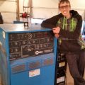
Get the ssc pedal and issues will all go away.
- 0902161427.jpg (38.83 KiB) Viewed 1197 times
why use standard nozzles after gas lens where invented. Kinda of like starting fires by rubbing sticks together.
- entity-unknown
-
Ace
-
Posts:
-
Joined:Mon Jul 18, 2016 2:07 pm
-
Location:Mesa, AZ
Hey Midget! I can't say I have any issues with my pedal. I do like the stock one and those clicks seemed like something reasonable to base some math on. Sam had an interesting point though that the POT is non-linear for the stock pedal so I'd never succeed to apply math unless I included the non-linear curve of the POT.
So as you, some others, and general reading suggest, the SSC is definitely the way to go if I ever do hope to consider developing some pre-calc math stuff to get me going when I'm dealing with metal, sizes, and geometry I haven't encountered.
I do have my Miller slide calculators which are very helpful but they are designed for generators, not inverters for the TIG one. Still it's a good baseline however it doesn't exactly get you anywhere special when you're using a pedal.
I really like those graphs Dave threw up. Granted it's for stick, the math/curves have legitimate relevance.
As said the ultimate goal is to somehow map the different metal types/grades, and their solidus/liquidus state in relation to the 9V perfect arc length perhaps with an upper/lower limit relative to short/good/long arcs, which maps to Thermal Conductivity based on material, geometry, 3d surface area, and correlates the necessary heat input plus travel speed which is then translated into a min/max Amps setting in relation to the desired foot pedal travel.... I know still have fun with that
Lincoln Electric AC225
Everlast PowerPro Multi-Process TIG/Stick/Plasma 256Si
Everlast W300 WaterCooler
Optrel e684x1
22+ Year Security Engineer developing cool shit and stoppin hackers
Everlast PowerPro Multi-Process TIG/Stick/Plasma 256Si
Everlast W300 WaterCooler
Optrel e684x1
22+ Year Security Engineer developing cool shit and stoppin hackers
- MinnesotaDave
-
Weldmonger
-
Posts:
-
Joined:Sun Oct 27, 2013 10:57 pm
-
Location:Big Lake/Monticello MN, U.S.A.
The slide calculators are not specifically for generators (engine drives).entity-unknown wrote: I do have my Miller slide calculators which are very helpful but they are designed for generators, not inverters for the TIG one. Still it's a good baseline however it doesn't exactly get you anywhere special when you're using a pedal.
I really like those graphs Dave threw up. Granted it's for stick, the math/curves have legitimate relevance.
As said the ultimate goal is to somehow map the different metal types/grades, and their solidus/liquidus state in relation to the 9V perfect arc length perhaps with an upper/lower limit relative to short/good/long arcs, which maps to Thermal Conductivity based on material, geometry, 3d surface area, and correlates the necessary heat input plus travel speed which is then translated into a min/max Amps setting in relation to the desired foot pedal travel.... I know still have fun with that
The graphs I put up are not only stick. The inverter shows stick and tig (notice dig did not apply to tig).
The tranny machine will change based on the volt/amp curve regardless of stick or tig.
Your math inquiry, while interesting, does not take into account that the material constantly increases in heat as you weld.
Therefore you are trying to quantify a moving target.
Much of what you do while welding is based on what you see while welding.
What you see dictates travel speed, more/less filler rod, more/less pedal, torch movement, etc..
Your pedal travel will become second nature and you won't even think about it after you gain a certain amount of experience.
The "optimum" settings are sometimes the same for different thicknesses when doing multiple passes.
Dave J.
Beware of false knowledge; it is more dangerous than ignorance. ~George Bernard Shaw~
Syncro 350
Invertec v250-s
Thermal Arc 161 and 300
MM210
Dialarc
Tried being normal once, didn't take....I think it was a Tuesday.
Beware of false knowledge; it is more dangerous than ignorance. ~George Bernard Shaw~
Syncro 350
Invertec v250-s
Thermal Arc 161 and 300
MM210
Dialarc
Tried being normal once, didn't take....I think it was a Tuesday.
- entity-unknown
-
Ace
-
Posts:
-
Joined:Mon Jul 18, 2016 2:07 pm
-
Location:Mesa, AZ
Hey Dave! I did realize the TIG part now on your graphs. I still like em and appreciate the post. This is still all soaking in but that's very handy to digest As for the slide calc I meant for transformers, not generators. The slide calc does say for inverters a 10% adjustment should be made.
The heat input (HI) (general math involved in my first post) and thermal conductivity (TC) (different per material which is in my first post) are the the portions that "would" address the moving target you're mentioning but that's part of the whole thing with the relation of how you taper off to keep that consistent amount of heat in the path of travel relative to the thermal conductivity of the material and all that 3d geometry in relation to area/angle of your parts while you're considering travel speed to adjust the HI in relation to TC.
There's a lot to consider and I know watching things is very important but what's happening below the surface could be arguably more important or at least that's where this train wreck thought is heading to. After seeing some of Larry Zirker's talks particularly the one about I believe the A513 steel weld on the low boy trailer that broke and killed someone; it made me feel this thought is very important. In short the welds would have looked beautiful and to most anyone even many non heavy structural welders it would have probably passed.
In short, we can make a beautiful weld that seems to hold up pretty good even with a good beating, but if we don't understand what we're doing to the material, and really understand how the material changes as we melt/weld it then we still might be doing it wrong. The application certainly dictates just how important this really is since welding pigs out of pipe for Christmas isn't exactly going to kill anyone
I'm also trying to learn the considerations of just how fast I should want to light up and get a puddle. SS seems to be immediately, AL seems to be pretty quick but debatable with AC Freq, and the general basic Mild Steel seems to not care as much but perhaps has a wider degree of change between annealing and hardening. 3d geometry of your fit up, surface plane of your parts, and travel path obviously all contribute.
I know for you I'm preaching to the choir but just sharing where and why I'm running with this
Lincoln Electric AC225
Everlast PowerPro Multi-Process TIG/Stick/Plasma 256Si
Everlast W300 WaterCooler
Optrel e684x1
22+ Year Security Engineer developing cool shit and stoppin hackers
Everlast PowerPro Multi-Process TIG/Stick/Plasma 256Si
Everlast W300 WaterCooler
Optrel e684x1
22+ Year Security Engineer developing cool shit and stoppin hackers
- entity-unknown
-
Ace
-
Posts:
-
Joined:Mon Jul 18, 2016 2:07 pm
-
Location:Mesa, AZ
So I just got my SSC pedal for my Everlast and I'm very happy with it but I'd say using some test parts before you fire up on a good piece is a wonderful idea because as Greintime told me, my original pedal was a non-linear potentiometer. The SSC is definitely linear and you can see/feel it.
I found I had to drop my usual Amp settings down and I was still getting the same, if not better results. The only "downside" is there's less travel but that probably equates to why I have to reduce the Amps since 1 degree of travel on this pedal is probably 120% or more of what one degree for the former pedal would have when dividing your max Amps set by the degrees of travel available. 100A with 25 degrees of travel equals 4 Amps per degree where 100 Amps with 20 degrees of travel equal 5 Amps per degree. 200A would be 8A vs. 10A.
Now toss a non-linear vs. a linear potentiometer in there and we find we can only apply that math to the SSC. It kinda got me by with the Everlast factory pedal, but WOW on the SSC. Definitely a learning curve but that's the only curve since the upslope is linear i.e. no slope in how power is transferred vs. the non-linear which has a curved upslope in how power is transferred. With that curved upslope, that means 70% press on the Everlast really could be more like 40-50% on the SSC simply because of the middle curve down slope for the factory pedal, vs. the linear/constant.
All said I think the SSC is definitely key to me building out that evil equation which hopefully can translate to a spreadsheet where you can select your metal type, some other variables including dimensions and angles and perhaps get some very useful settings spit back at you.
DUDE YOU MAKE NO SENSE!!!
Here's a pic to describe this babble. The Everlast would be the blue line, the SSC is the black.
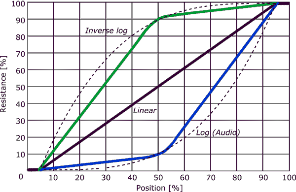
Lincoln Electric AC225
Everlast PowerPro Multi-Process TIG/Stick/Plasma 256Si
Everlast W300 WaterCooler
Optrel e684x1
22+ Year Security Engineer developing cool shit and stoppin hackers
Everlast PowerPro Multi-Process TIG/Stick/Plasma 256Si
Everlast W300 WaterCooler
Optrel e684x1
22+ Year Security Engineer developing cool shit and stoppin hackers
GreinTime
- GreinTime
-
Weldmonger
-
Posts:
-
Joined:Fri Nov 01, 2013 11:20 am
-
Location:Pittsburgh, PA
I just ordered an SSC pedal about 20 minutes ago, it should be here by Wednesday. I was welding some stainless exhaust pieces for a buddy of mine today and wasn't happy with the lack of control I had due to a failing potentiometer. You think using the pedal is bad as it is, trying doing all of your welding using different ranges in the pedal where you actually have some resolution, and then remembering where they are, or else the welder drops to 7a... It was a trying, harrowing experience. At least with lift arc the amps would have stayed the same!
Sent from my SM-G900V using Tapatalk
Sent from my SM-G900V using Tapatalk
#oneleggedproblems
-=Sam=-
-=Sam=-
Return to “Tig Welding - Tig Welding Aluminum - Tig Welding Techniques - Aluminum Tig Welding”
Jump to
- Introductions & How to Use the Forum
- ↳ Welcome!
- ↳ Member Introductions
- ↳ How to Use the Forum
- ↳ Moderator Applications
- Welding Discussion
- ↳ Metal Cutting
- ↳ Tig Welding - Tig Welding Aluminum - Tig Welding Techniques - Aluminum Tig Welding
- ↳ Mig and Flux Core - gas metal arc welding & flux cored arc welding
- ↳ Stick Welding/Arc Welding - Shielded Metal Arc Welding
- ↳ Welding Forum General Shop Talk
- ↳ Welding Certification - Stick/Arc Welding, Tig Welding, Mig Welding Certification tests - Welding Tests of all kinds
- ↳ Welding Projects - Welding project Ideas - Welding project plans
- ↳ Product Reviews
- ↳ Fuel Gas Heating
- Welding Tips & Tricks
- ↳ Video Discussion
- ↳ Wish List
- Announcements & Feedback
- ↳ Forum News
- ↳ Suggestions, Feedback and Support
- Welding Marketplace
- ↳ Welding Jobs - Industrial Welding Jobs - Pipe Welding Jobs - Tig Welding Jobs
- ↳ Classifieds - Buy, Sell, Trade Used Welding Equipment
- Welding Resources
- ↳ Tradeshows, Seminars and Events
- ↳ The Welding Library
- ↳ Education Opportunities